
Ke Zhang, Zhaoxi Chen, Hanke Feng, Wing-Han Wong, Edwin Yue-Bun Pun, Cheng Wang. High-Q lithium niobate microring resonators using lift-off metallic masks [Invited][J]. Chinese Optics Letters, 2021, 19(6): 060010
- Chinese Optics Letters
- Vol. 19, Issue 6, 060010 (2021)
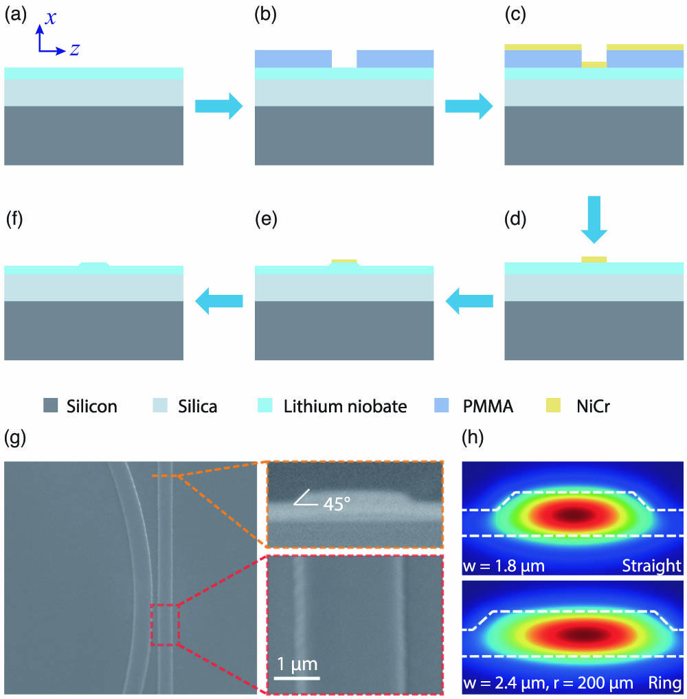
Fig. 1. (a)–(f) Device fabrication flowchart. (a) Fabrication starts with an x-cut LNOI substrate. (b) PMMA resist is first spin-coated and patterned with EBL. (c) NiCr etching mask is subsequently created by thermal evaporation, (d) followed by a standard lift-off process. (e) The patterned NiCr is then used as an etching mask to form the LN waveguides using an Ar+-based RIE process. (f) The residual NiCr is finally removed in Cr etchant. (g) SEM images of a fabricated microring resonator and a coupling bus waveguide. Insets show magnified cross-section (top) and top-down (bottom) views of the bus waveguide. (h) Simulated electric field (Ez) profiles of the fundamental TE modes in the straight bus waveguide (top) and the bending ring waveguide (bottom).
![Step-by-step SEM examinations of the lift-off processes. (a), (b) Cross-section profiles of the PMMA resist after EBL. (c), (d) Cross-section profiles after thermal evaporation. (e), (f) Top-down views of the final NiCr masks. The left column [(a), (c), and (e)] shows a typical unoptimized lift-off process with overcut resist profiles and mask fencing features, whereas the right column [(b), (d), and (f)] corresponds to the optimized process with smooth mask profiles. The left part of PMMA resist in (c) was accidentally detached from the substrate during the cleaving step.](/richHtml/col/2021/19/6/060010/img_002.jpg)
Fig. 2. Step-by-step SEM examinations of the lift-off processes. (a), (b) Cross-section profiles of the PMMA resist after EBL. (c), (d) Cross-section profiles after thermal evaporation. (e), (f) Top-down views of the final NiCr masks. The left column [(a), (c), and (e)] shows a typical unoptimized lift-off process with overcut resist profiles and mask fencing features, whereas the right column [(b), (d), and (f)] corresponds to the optimized process with smooth mask profiles. The left part of PMMA resist in (c) was accidentally detached from the substrate during the cleaving step.
Fig. 3. (a) Experimental setup for LN microring resonator characterization. FPC, fiber polarization controller; DUT, device under test; PD, photodetector. Measured optical transmission spectra for typical microring resonators using (b) unoptimized and (c) optimized fabrication processes. (d) and (e) Zoom-in views of (b) and (c) showing critically coupled resonances. Blue dots show the measured data, and red curves correspond to the Lorentzian fits, indicating intrinsic Q factors of 1.4 × 10⁵ and 1.1 × 10⁶ for unoptimized and optimized metallic masks, respectively.

Set citation alerts for the article
Please enter your email address
© Copyright 2018-2021 | Chinese Laser Press. All Rights Reserved 沪ICP备15018463号-20