
Lu Fang, Qionghai Dai. Computational Light Field Imaging[J]. Acta Optica Sinica, 2020, 40(1): 0111001
- Acta Optica Sinica
- Vol. 40, Issue 1, 0111001 (2020)
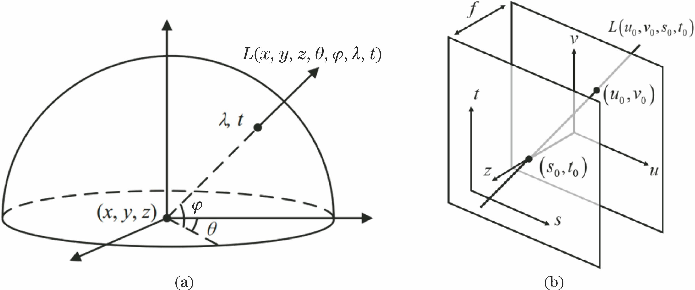
Fig. 1. Schematics of (a) the seven-dimensional plenoptic function and (b) the four-dimensional simplified light field
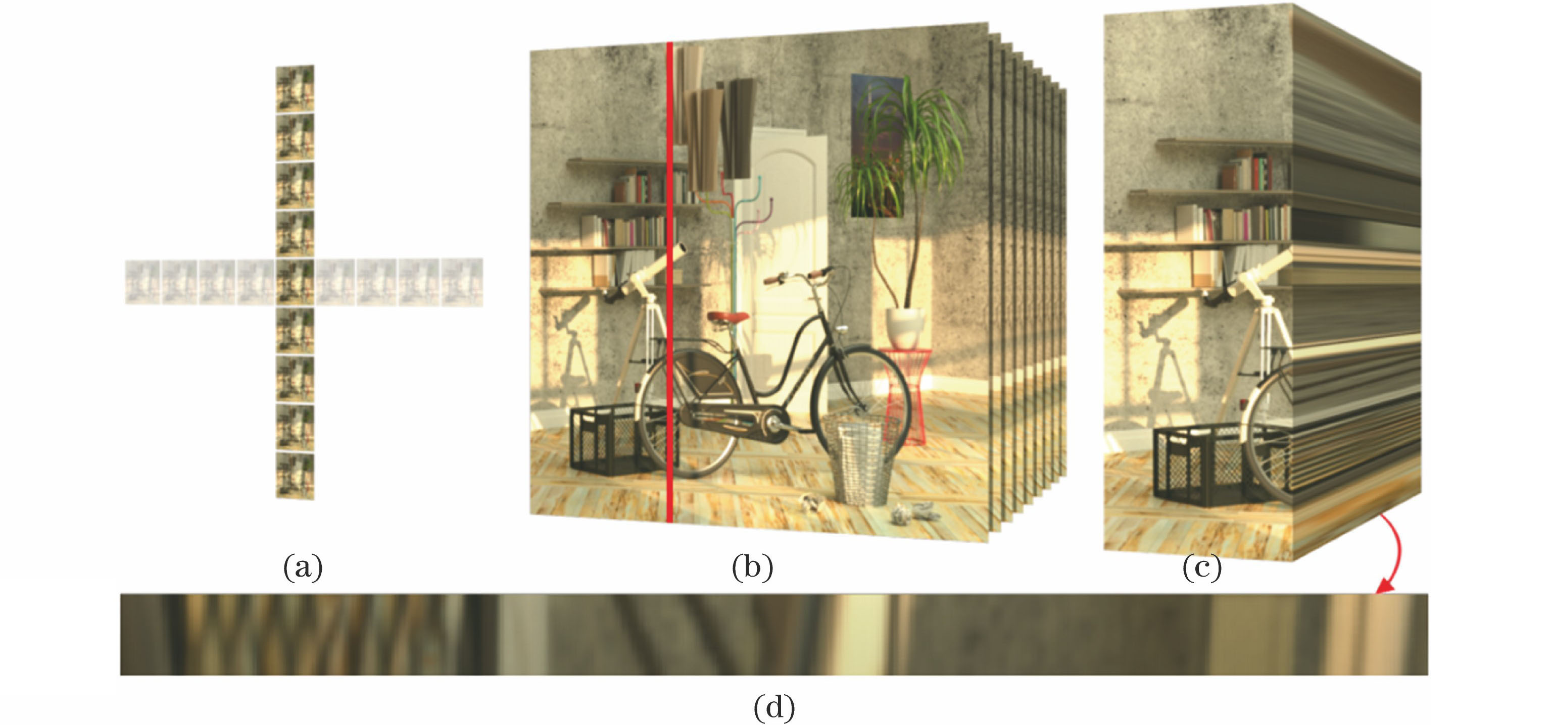
Fig. 2. Characterization of the four-dimensional light field. (a) Sub-aperture image
Fig. 3. Virtual light field rendering with the collected spherical space
Fig. 4. Light field rendering with dual-plane interpolation in the four-dimensional light field
Fig. 5. Devices for multiple-sensor acquisition. (a) Camera array system composed of 8×12 cameras, developed by Wilburn et al.[17]; (b) real-time light field rendering realized by the 8×8 camera array, constructed by Yang et al.[18]; (c) light field camera array with size of 90 mm×90 mm×60 mm, manufactured by ViewPLUS; (d) PiCam, developed by Venkataraman et al.[19![(a) Light field setup and (b) optical path schematic for acquiring micro-object images with the 5×5 camera array system[22]](/Images/icon/loading.gif)
Fig. 6. (a) Light field setup and (b) optical path schematic for acquiring micro-object images with the 5×5 camera array system[22]
Fig. 7. Devices for timing sequence collection. (a) Light field framework, constructed by the Stanford University in 1996, to realize collection of the static light field by controlling all degrees of freedom including object, camera, and illumination[3]; (b) electric linear stage, constructed by Unger et al.[27], assembling a single camera for capturing the four-dimensional light field; (c) programmable a
Fig. 8. Devices for multi-channel imaging. (a) Microlens light field camera and its principle[35]; (b) light field microscope based on the microlens array, developed by the Stanford University[7]; (c) multiple reflective sphere light field acquisition device, developed by Lanman et al.[42]; (d) light field multiplexing acquisition method based on masks, dev
Fig. 9. Giga-pixel image acquisition device Gigapan and stitched panoramas with 1.5×108 pixels[58]
Fig. 10. Prototype of gigapixel multiscale camera[60]
Fig. 11. AWARE-2 camera array and imaging results[62]
Fig. 12. In-parallel single-photocenter camera array composed of three single-photocenter spherical multiscale camera arrays[65]
Fig. 13. Wide-field-of-view light field imaging based on single-photocenter spherical arrayed camera and light field camera
Fig. 14. Hybrid light field high-resolution computational imaging system
Fig. 15. Data density example of a natural scenario. (a) The image is divided into 8×8 pieces spatially and the sum of high-frequency coefficients is used to represent the spatial information density; (b) data density is represented temporally by the entropy of each pixel signal along the time axis; (c) semantic data density is represented by the high-level information distribution labeled with the tested people boundaries and vehicle boundaries
Fig. 16. Image sensor array. (a) Conventional structured image sensor array; (b) unstructured image sensor array
Fig. 17. Unstructured heterogeneous image sensor array[68]
Fig. 18. Reconstructing high-resolution light field by sparse angle dimension sampling
Fig. 19. Flow chart of typical view blending based on depth map
Fig. 20. Disparity estimation and color prediction via two CNNs
Fig. 21. Multi-plane decomposition and color prediction of light field by sparse angle-of-view sampling
Fig. 22. Light field reconstruction, circumventing explicit disparity, has excellent effect on the non-Lambert area. (a) EPI based on disparity estimation; (b) reconstructed EPI circumventing explicit disparity; (c) target EPI
Fig. 23. Classical frequency-domain light field reconstruction. (a) Typical aliasing resulting from light field under-sampling; (b) light field reconstruction by using anti-aliasing filter (shown as the red quadrangle)
Fig. 24. Light field reconstruction via EPI. (a) Extract low-frequency components in the EPI spatial dimension for anti-aliasing before input into the deep neural network; (b) recover information in the angle dimension through the deep neural network; (c) recover information in the EPI spatial dimension through non-blind deconvolution
Fig. 25. Light field reconstruction in the microscopic scenario with input and output light field angle-of-view resolutions of 3×3 and 7×7, respectively. The top right shows the output reported by Wu et al.[83] and the bottom right shows the target result

Set citation alerts for the article
Please enter your email address
© Copyright 2018-2021 | Chinese Laser Press. All Rights Reserved 沪ICP备15018463号-20