
Yonghong Wang, Yilei Zhu, Qixue Gao, Huanqing Wang. Position and Pose Measurement of Spatial Object Based on Digital Image Correlation[J]. Acta Optica Sinica, 2022, 42(8): 0812001
- Acta Optica Sinica
- Vol. 42, Issue 8, 0812001 (2022)
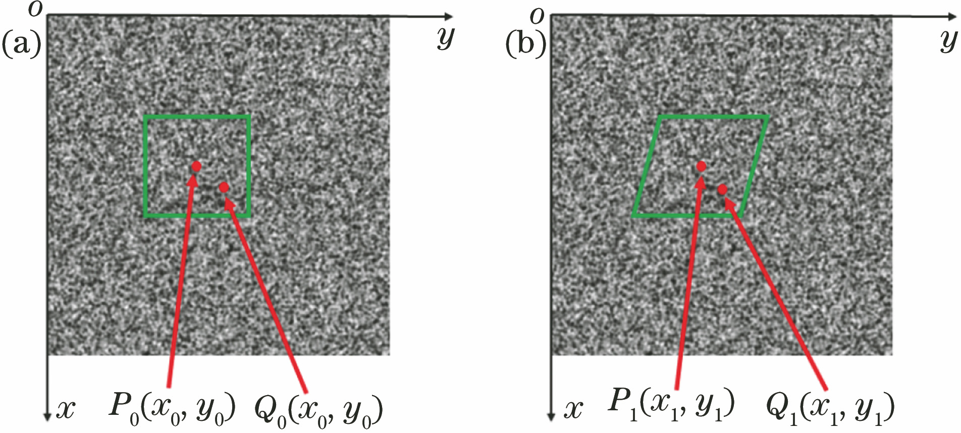
Fig. 1. Principle of DIC. (a) Reference image; (b) deformed image
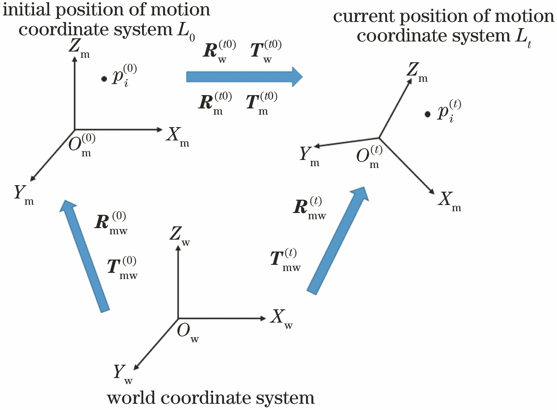
Fig. 2. Coordinate system conversion in stereo vision measurement system
Fig. 3. Physical graphs of measured object and measurement system. (a) Mask sample; (b) position and pose measurement system of mask sample on translation and rotation stage
Fig. 4. Relative error of calculation points of different numbers for mask sample on translation and rotation stage. (a) Transverse shift; (b) longitudinal shift; (c) elevation and subsidence; (d) yaw
Fig. 5. Relative error of calculation points of optimal number for different M. (a) Transverse shift; (b) longitudinal shift; (c) elevation and subsidence; (d) yaw
Fig. 6. Relative error of calculation points at different positions for mask sample on translation and rotation stage. (a) Transverse shift; (b) longitudinal shift; (c) elevation and subsidence; (d) yaw
Fig. 7. Schematic diagram of measurement system of position and pose of six degree-of-freedom platform
Fig. 8. Position and pose measurement system for mask sample on six degree-of-freedom platform
|
Table 1. Parameters of six degree-of-freedom platform
| ||||||||||||||||||||||||||||||||||||||||||||||||||||||||||||||||||||||||||||||||||||||||||||||||||||||||||||||||||||
Table 2. Measurement results of displacement parameters of mask samplemm
| ||||||||||||||||||||||||||||||||||||||||||||||||||||||||||||||||||||||||||||||||||||||||||||||||||||||||||||||||||||||||||||||||||||||||||||
Table 3. Measurement results of rotation parameters of mask sample(°)

Set citation alerts for the article
Please enter your email address
© Copyright 2018-2021 | Chinese Laser Press. All Rights Reserved 沪ICP备15018463号-20