
Yuezhen Sun, Zhijun Yan, Qizhen Sun, Kaiming Zhou, Lin Zhang. Research Progress of Excessively Tilted Fiber Grating[J]. Laser & Optoelectronics Progress, 2021, 58(13): 1306013
- Laser & Optoelectronics Progress
- Vol. 58, Issue 13, 1306013 (2021)
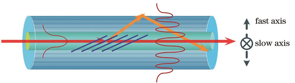
Fig. 1. Schematic diagram of Ex-TFG structure
![Mode coupling simulation results of Ex-TFG. (a) Coupling coefficients of different cladding modes with l=1,2,3 in Ex-TFG[26]; (b) field distribution in Ex-TFG cladding mode](/richHtml/lop/2021/58/13/1306013/img_2.jpg)
Fig. 2. Mode coupling simulation results of Ex-TFG. (a) Coupling coefficients of different cladding modes with l=1,2,3 in Ex-TFG[26]; (b) field distribution in Ex-TFG cladding mode
Fig. 3. Cladding mode effective indexes of TE and TM modes[21]
Fig. 4. Resonance wavelengths versus axial periods of Ex-TFG with TE (solid line) and TM (dash line) modes for different orders[23]. (a) m is in the range of 1‒9; (b) m is in the range of 10‒20; (c) m is in the range of 21‒30; (d) m is in the range of 29‒45
Fig. 5. Waveguide dispersion factors
Fig. 6. Schematic diagrams of Ex-TFG inscription[23]. (a) Front view; (b) top view of amplitude mask and fiber with 0 order diffraction inside fiber core
Fig. 7. Transmission spectra of Ex-TFG with 81° tilt angle[23]. (a) A series of dual-peak resonances in 1300‒1700 nm; (b) one pair of dual-peaks measured by linear polarization light with different azimuth angles
Fig. 8. Spectra measurement of integrated TFG. (a) Experimental setup for Ex-TFG transmission spectra measurement with different linear polarizations[23]; (b) transmission spectra of 81°-TFG measured by coupling a linear polarization light with different azimuth angles with respect to fast axis of grating[23]; (c) microscopy images of hybrid 45°-TFG and 81°-TFG[35]; (d) transmission spectra of hybrid 45°-TFG and 81°-TFG[35]
Fig. 9. Refractive index sensing experiment of Ex-TFG. (a) Refractive index sensitivies for TE and TM modes with different cladding radii[22]; (b) refractive index sensitivies for TM modes with different cladding mode orders[24]
Fig. 10. Vector sensing experiment of Ex-TFG[26]. (a) Near field light field distribution of Ex-TFG; (b) schematic diagram of Ex-TFG by sidely immersing; (c) transmission spectral responses for TM mode of Ex-TFG by sidely immersing and totally immersing; (d) wavelength shifts for TM cladding mode along different immersion angles
Fig. 11. Temperature sensitivities of Ex-TFG with different cladding mode orders[24]
|
Table 1. Effective refractive indexes and refractive index sensitivities for TM modes of Ex-TFG with different tilt angles
|
Table 2. Effective refractive indexes and temperature sensitivities for TM modes of Ex-TFG with different tilt angles

Set citation alerts for the article
Please enter your email address
© Copyright 2018-2021 | Chinese Laser Press. All Rights Reserved 沪ICP备15018463号-20