• Chinese Optics Letters
  • Vol. 21, Issue 10, 101302 (2023)
Jialang Zhang1, Siyuan Zhang1, Junna Yao1, Xinhua Jiang1, Anting Wang1、*, and Qiwen Zhan2
Author Affiliations
  • 1Department of Optics and Optical Engineering, University of Science and Technology of China, Hefei 230026, China
  • 2School of Optical-Electrical and Computer Engineering, University of Shanghai for Science and Technology, Shanghai 200093, China
  • show less
    DOI: 10.3788/COL202321.101302 Cite this Article Set citation alerts
    Jialang Zhang, Siyuan Zhang, Junna Yao, Xinhua Jiang, Anting Wang, Qiwen Zhan. Slotless dispersion-flattened waveguides with more than five zero-dispersion wavelengths[J]. Chinese Optics Letters, 2023, 21(10): 101302 Copy Citation Text show less
    Structure diagram of the dispersion-flattened waveguide.
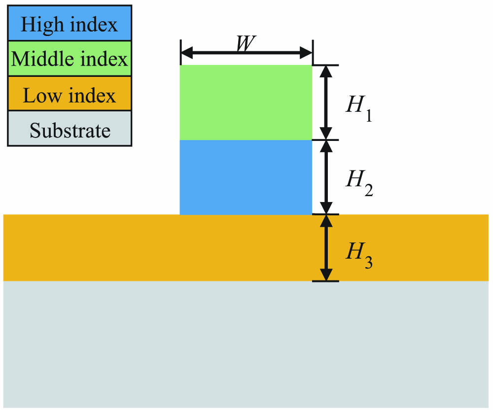
    Fig. 1. Structure diagram of the dispersion-flattened waveguide.
    (a)–(c) Principle of dispersion flattening for the proposed waveguides; optical intensity distribution of the guided mode at (d) 2500 nm; (e) 3500 nm; (f) 4500 nm; (g) 5500 nm.
    Fig. 2. (a)–(c) Principle of dispersion flattening for the proposed waveguides; optical intensity distribution of the guided mode at (d) 2500 nm; (e) 3500 nm; (f) 4500 nm; (g) 5500 nm.
    Ultraflat dispersion and confinement loss of the guided mode of (a) WG1 and (b) WG2; mode concentration in upper strip, lower strip, and slab layer of (c) WG1 and (d) WG2.
    Fig. 3. Ultraflat dispersion and confinement loss of the guided mode of (a) WG1 and (b) WG2; mode concentration in upper strip, lower strip, and slab layer of (c) WG1 and (d) WG2.
    Dispersion profile of WG1 with different structural parameters changed by 1% each time around the optimum values. (a) Different W, (b) different H1, (c) different H2, and (d) different H3.
    Fig. 4. Dispersion profile of WG1 with different structural parameters changed by 1% each time around the optimum values. (a) Different W, (b) different H1, (c) different H2, and (d) different H3.
    (a) Mode overlap factor with one mode located at 3300 nm, Aeff, and γ of WG1; (b) mode overlap factor with one mode located at 4140 nm, Aeff, and γ of WG2.
    Fig. 5. (a) Mode overlap factor with one mode located at 3300 nm, Aeff, and γ of WG1; (b) mode overlap factor with one mode located at 4140 nm, Aeff, and γ of WG2.
    YearZDWDispersion (ps/(nm·km))Wavelength (nm)Flatness (nm2·km/ps)
    2016[21]4−15.87 to 11.341520–232029.40
    2016[21]4−4.73 to 5.691660–3290156.73
    2018[9]4−16 to 323500–10,000135.42
    2018[22]5−18 to 142600–15,500403.13
    2019[12]4−0.98 to 0.981670–2245293.37
    2021[6]2−24.13 to 71.171000–350026.23
    2022[23]10 to 271290–4570121.48
    2022[24]4−1 to 11810–3630910
    This work6−1.2 to 1.11980–48801260.87
    This work5−0.472 to 0.3652885–55503183.99
    Table 1. Comparison of Dispersion-Flattened Waveguides without the Slot-Assisted Structures in Recent Work
    Jialang Zhang, Siyuan Zhang, Junna Yao, Xinhua Jiang, Anting Wang, Qiwen Zhan. Slotless dispersion-flattened waveguides with more than five zero-dispersion wavelengths[J]. Chinese Optics Letters, 2023, 21(10): 101302
    Download Citation