• Acta Optica Sinica
  • Vol. 41, Issue 7, 0722002 (2021)
Lingying Chang1, Qiang Zhang1、*, and Yuehong Qiu2
Author Affiliations
  • 1School of Electronic Engineering, Xi′an University of Posts & Telecommunications, Xi′an, Shaanxi 710121, China;
  • 2Xi′an Institute of Optics and Precision Mechanics, Chinese Academy of Sciences, Xi′an, Shaanxi 710119, China
  • show less
    DOI: 10.3788/AOS202141.0722002 Cite this Article Set citation alerts
    Lingying Chang, Qiang Zhang, Yuehong Qiu. Design of Optical System for Broadband and Integrated AOTF Imaging Spectrometer[J]. Acta Optica Sinica, 2021, 41(7): 0722002 Copy Citation Text show less
    Framework of AOTF imaging spectrometer
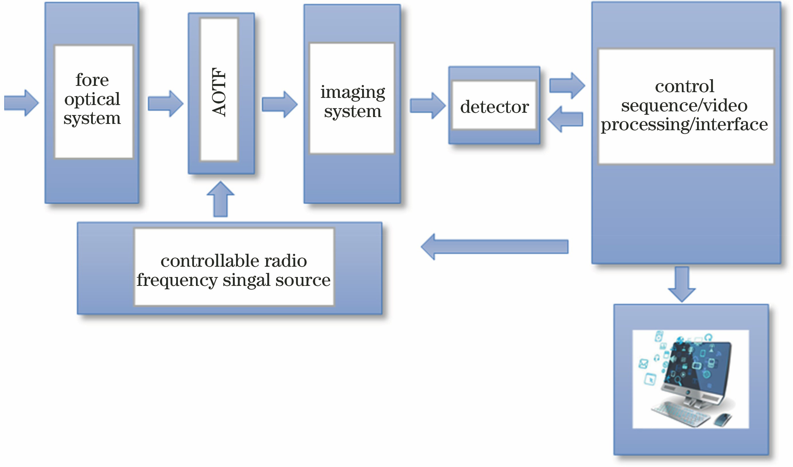
    Fig. 1. Framework of AOTF imaging spectrometer
    Schematic AOTF
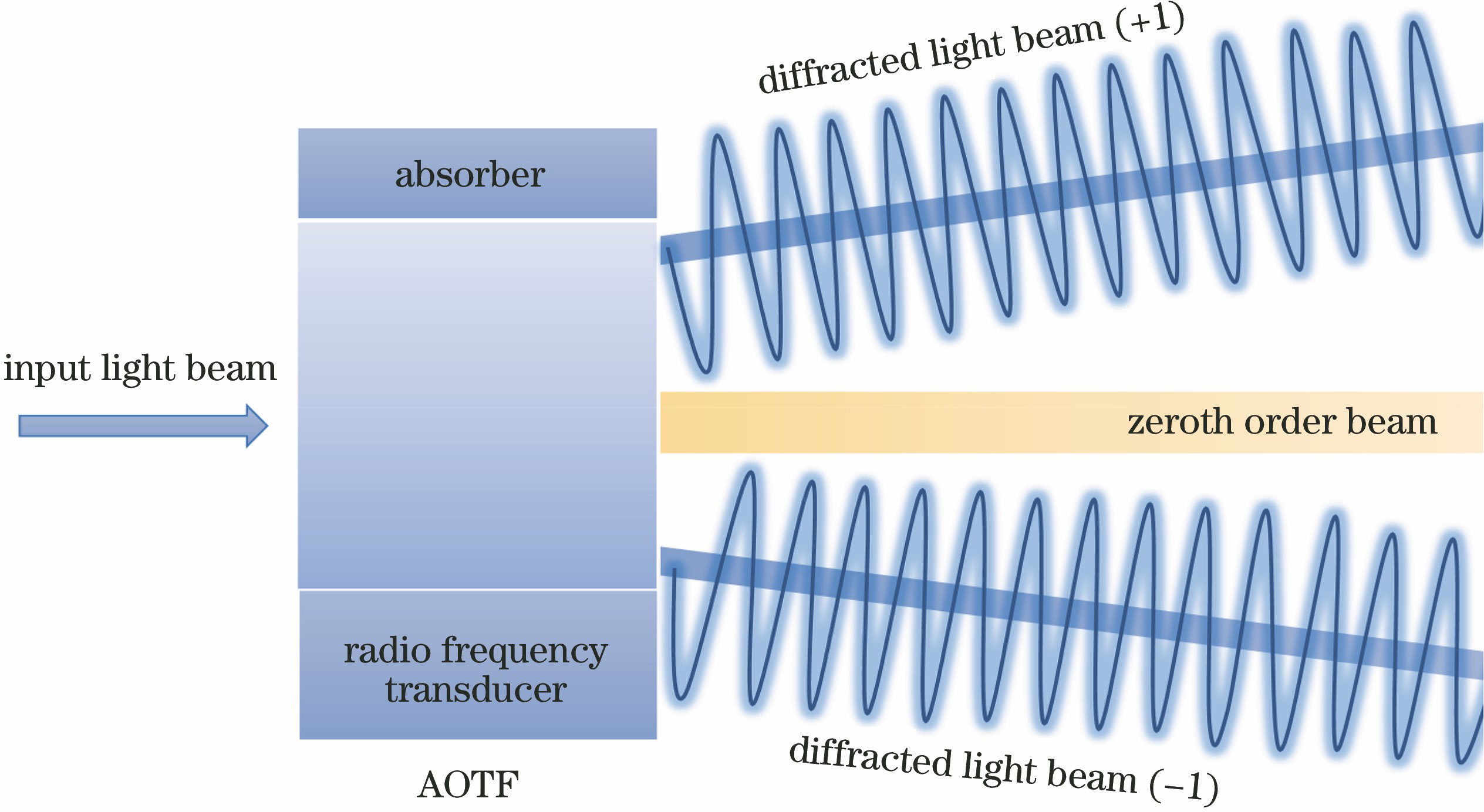
    Fig. 2. Schematic AOTF
    Layout diagram of whole optical system
    Fig. 3. Layout diagram of whole optical system
    Structure of optical system
    Fig. 4. Structure of optical system
    MTF curves of each wave band. (a) 0.4--1.0 μm; (b) 1.0--3.0 μm; (c) 3.0--5.0 μm
    Fig. 5. MTF curves of each wave band. (a) 0.4--1.0 μm; (b) 1.0--3.0 μm; (c) 3.0--5.0 μm
    Distortion curve of optical system
    Fig. 6. Distortion curve of optical system
    Ray aberration curves of optical system
    Fig. 7. Ray aberration curves of optical system
    Type of CCDWavelength /μmResolution ratio /(pixel×pixel)Pixel size /μmManufacturer
    C9100-23BC10633-34LCT6500.4--1.01.0--3.03.0--5.0512×512640×512640×480162028HamamatsuHamamatsuLMT
    Table 1. Parameters of CCD
    Optical systemf' /mmF2ω /(°)Special requirement
    Front optical system12555.3/
    Collimating system12555.3The aperture stop is in front
    AOTF///The whole system aperture stop is located on it
    Imaging system12555.3The aperture stop is in front
    Table 2. Optical parameters of each optical system
    ParameterM1M2M3
    Decentration /mm-2.259.71-42.62
    Tilt /(°)-8.8514.94-9.46
    Conic constant-0.0057-0.59710.2905
    4th order coefficient3.2099×10-81.1255×10-74.5249×10-9
    6th order coefficient6.8373×10-13-7.0802×10⁻¹²-1.3881×10⁻¹²
    Table 3. Decentration and tilt of each mirror in collimation system and imaging system
    ParameterM5M6
    x2-0.0002106972160320470.000255701901033404
    y2-0.00171804160559217-0.000236872764458664
    x2y9.04570554409036×10-56.20840490996327×10⁻⁵
    y32.00886732732122×10-52.4067793728652×10⁻⁵
    x48.14765363997121×10-71.11814320160958×10⁻⁶
    x2y21.07561516752013×10-61.93207601895823×10⁻⁶
    y4-5.15133651906762×10-76.9508661703245×10-8
    x2y31.63554420207729×10-77.35226113716151×10⁻⁸
    x4y1.06110204783277×10-76.55137454872012×10⁻⁸
    y54.59026670330349×10-84.82190236092222×10⁻⁹
    x62.94401246962391×10-9-1.98161446537076×10⁻¹⁰
    x4y26.81970754121763×10-91.71051475340913×10⁻⁹
    x2y43.89696710828571×10-91.0572403532361×10⁻⁹
    y66.27978015435262×10-103.26946542626363×10⁻¹²
    Table 4. Free-form surface parameters of 2th and 3th mirrors of front optical system
    ParameterM4M5M6
    Decentration /mm-50.0013.5131.97
    Tilt /(°)-10.989.7615.39
    Table 5. Decentration and tilt of each mirror of front optical system
    Spatialfrequency /(lp·mm-1)Spectralband /μmWavelength /μmMTF
    500.4--1.00.40.50.70.91.00.7870.7710.7070.6510.621
    201.0--3.01.01.52.02.53.00.8450.7780.7110.6430.577
    123.0--5.03.03.54.04.55.00.7420.7010.6590.6190.579
    Table 6. MTF values of whole optical system
    Lingying Chang, Qiang Zhang, Yuehong Qiu. Design of Optical System for Broadband and Integrated AOTF Imaging Spectrometer[J]. Acta Optica Sinica, 2021, 41(7): 0722002
    Download Citation