Ping Zhu, Xinglong Xie, Jun Kang, Qingwei Yang, Haidong Zhu, Ailin Guo, Meizhi Sun, Qi Gao, Ziruo Cui, Xiao Liang, Shunhua Yang, Dongjun Zhang, Jianqiang Zhu. Systematic study of spatiotemporal influences on temporal contrast in the focal region in large-aperture broadband ultrashort petawatt lasers[J]. High Power Laser Science and Engineering, 2018, 6(1): 010000e8
Copy Citation Text
Temporal contrast is one of the crucial physical determinants which guarantee the successful performance of laser–matter interaction experiments. We generally reviewed the influences on the temporal contrast in three categories of noises based on the requirement by the physical mechanisms. The spatiotemporal influences on temporal contrast at the focal region of the chromatic aberration and propagation time difference introduced by large-aperture broadband spatial filters, which were spatiotemporally coupled with compression and focusing, were calculated and discussed with a practical case in SG-II 5 PW ultrashort petawatt laser. The system-wide spatiotemporal coupling existing in large-aperture broadband ultrashort petawatt lasers was proved to be one of the possible causes of temporal contrast degradation in the focal region.
In the past three decades, the development of ultrashort pulse laser techniques, such as broad spectrum pulse generation and chirped pulse amplification (CPA)[1], has brought up more than 50 petawatt-class high-power laser systems around the world, including glass laser systems, Ti: sapphire CPA lasers, optical parametric chirped pulse amplification (OPCPA) systems and diode-pumped laser systems, which have been established not only in the big national laboratories, but also in many university labs[2]. With the extremely high focused intensity, such high-power lasers can create special physical conditions for inertial confinement fusion (ICF), laser driven particle acceleration, and new radiation source generation[3]. The successful performances of these potential applications require high spatiotemporal qualities of the laser beam, comprising near-field beam profile, focusing Strehl ratio, pulse width and temporal contrast. While most characterizations of the laser beam can be well controlled by several improving techniques[4], temporal contrast, which is the ratio between the peak power of the main pulse and the intensity of the noise before the main pulse, remains still a tough issue. Meanwhile, the temporal contrast at the focal region needs more attention than that in the near field, because, if the focused intensity of the noise exceeds $10^{11}~\text{W}/\text{cm}^{2}$, pre-plasma will be produced[5] and the target may get evaporated before the main pulse arrives, which could lead to poor experimental results. The influence of temporal contrast has been demonstrated and studied experimentally[6, 7] and the enhanced performances of the experiments have been obtained with high temporal contrast[8, 9]. Furthermore, when the intensity of the laser becomes higher, the requirement of temporal contrast by experiments goes up accordingly. Hence, many efforts have been made to find out the spectral and temporal limitations of the separate components in an ultrashort pulse laser system[10] and their influence on temporal contrast is reviewed in Section 2.
From the perspective of the whole system, in addition to these spectral and temporal influences, there are ineluctable spatiotemporal couplings[11] or so-called spatiotemporal distortions existing in petawatt-class lasers, since such laser systems usually have large apertures and broad spectra. For example, the spatial filters (SFs) in such a large-aperture laser are designed for image relaying, beam expanding, and high-frequency noise filtering, but in such a broadband system, the spatial filters introduce chromatic aberration and propagation time difference (PTD) or radial group delay (RGD) into the input pulse, resulting in a spatiotemporally distorted one. The spatiotemporal distortions introduced by every single functional unit of the laser system can affect the final temporal contrast as well, such as the spatiotemporal coupling during the focusing, which is proved to be able to convert the spatial high-frequency noise in the near field to temporal noise of the pulse at the focal region[12]. The system-wide spatiotemporal coupling makes the situation more complex and degrades the temporal contrast at the focal region worse. However, such system-wide spatiotemporal influences have not been reported yet and it deserves more concern. Therefore, a systematic study of spatiotemporal influences on temporal contrast at the focal region in large-aperture broadband ultrashort petawatt lasers is necessary for comprehensively understanding the temporal contrast degradation and efficiently improving the temporal contrast.
In this paper, we reviewed three kinds of noises influencing the temporal contrast of a high-power ultrashort pulse based on the requirement of temporal contrast in physical experiments and summarized their possible causes in high-power ultrashort laser systems. Moreover, we pointed out a new temporal contrast degradation caused by the system-wide spatiotemporal coupling with a practical case of SG-II 5 PW large-aperture broadband ultrashort petawatt laser, and calculated the influence on temporal contrast at the focal region due to the chromatic aberration and PTD introduced by spatial filters spatiotemporally coupled with compression and focusing.
Sign up for High Power Laser Science and Engineering TOC. Get the latest issue of High Power Laser Science and Engineering delivered right to you!Sign up now
2 Review of the temporal contrast degradation
In order to make sure the best performance of the interaction between high-power laser pulse and the target in a physical experiment, the requirement of the temporal contrast has been put forward based on preventing the formation of unwanted pre-plasma before the main pulse reaches the target. There are two main physical mechanisms of target damage: one is absorption effect of long-duration pulses (nanoseconds) corresponding to ablation and melting, and the other one is ionization effect by short duration pulses (few picoseconds) leading to generation and expansion of pre-plasma[13]. Therefore, it is required that the final pulse at the focal region has a low nanosecond-scale noise and a high steepness of the front edge within picosecond range.
In a high-power ultrashort laser system, the seed pulse with broad spectrum is usually stretched into the nanosecond chirped pulse and sent through the multiple amplifiers. The final amplified chirped pulse is compressed back to femtosecond or picosecond pulse with high energy, whose peak power can reach petawatt, but the temporal contrast of the pulse after amplification and compression always gets deteriorated, unfortunately turning an originally perfect pulse into a noisy one. According to the two target damage mechanisms mentioned above, generally, three kinds of noises distributed in the two time domains (nanosecond range and picosecond range), namely pedestal noise, pre-pulse noise and coherent noise, contribute to the temporal contrast degradation. Their temporal features and their primary causes in the laser system are reviewed here.
2.1 Pedestal noise: amplified spontaneous emission and parametric fluorescence
In the pulse with temporal contrast degradation, a pedestal always can be seen before the main pulse, appearing as a temporally long noise background. In CPA laser system, the major source of such pedestal noise is amplified spontaneous emission (ASE)[14] with the duration of nanosecond range, while in OPCPA laser system parametric fluorescence (PF)[15, 16] mostly contributes to this noise background, whose duration is equal to the temporal length of the pump. In both cases, these pedestal noises are inherent with the amplifications and the typical number of the temporal contrast between the intensities of such pedestal noise and the main pulse is ${\sim}10^{7}$. Although the intensity of such nanosecond-scale pedestal noise might be rather low compared to the ionization threshold of the targets in some physical experiments, the accumulated energy over such a long noise duration can exceed the absorption fluence threshold of the targets, resulting ablation and melting[10].
2.2 Pre-pulse noise: imperfect optics and nonlinear effects
Apart from the long-duration pedestal noise, the nanosecond-scale temporal contrast can also be deteriorated by some noise peaks that precedes the main pulse, called pre-pulses. On the one hand, since the optics in the laser system can hardly be perfect, the pre-pulses as well as post-pulses can be introduced in a linear way by scattering of imperfect reflective and diffractive optics, birefringence of imperfect transmitting optics, or leaking of polarizing optics. Petawatt laser systems should be carefully designed to avoid such linear pre-pulses, but usually the post-pulses still exist. On the other hand, in a nonlinear way, the post-pulses with less attention will generate satellite pulses related to the nonlinearity of the refractive index and gain, especially in the multiple-pass amplifiers and regenerative amplifiers[17]. In petawatt pulses, the intensity of such pre-pulses from the nonlinear generation can be quite strong and easily reach the ionization threshold of the target. As a result, considerable and undesired pre-plasma will be produced and degenerate the performance of the physical experiments.
2.3 Coherent noise: spectral amplitude and phase modulation
The picosecond-scale temporal contrast is determined by the steepness of the leading edge of a pulse, which is associated with the wing-shape coherent noise around the main pulse. Many research efforts have been made to find out various influences in the laser systems responding to this coherent noise. Principally, such coherent noise is resulted from the spectral amplitude and phase modulation, but for different laser systems, the specific causes comprise spectral clipping[10], high order dispersion[18], pump-induced noise in OPCPA system[19–21] and spatiotemporal coupling such as inhomogeneous amplification[22], and spatial-to-spectral phase coupling[23]. All these influences work separately or simultaneously, flattening the steepness and degrading the picosecond-scale temporal contrast of the recompressed pulse. The resulting slow rise of the main pulse can cause the plasma hydrodynamic expansion of the sensitive target and change the supposed laser–matter interaction conditions.
3 Influence of system-wide spatiotemporal coupling
Besides the above influences on temporal contrast that we have reviewed, the systematic spatiotemporal couplings or distortions, such as chromatic aberration and RGD, can cause temporal contrast degradation. To demonstrate this influence, we take SG-II 5 PW large-aperture broadband ultrashort laser system as an example to investigate how the temporal contrast at the focal region is deteriorated when such system-wide spatiotemporal distortions are introduced in a high-power ultrashort laser system.
3.1 Lens-based spatial filters in SG-II 5 PW laser system
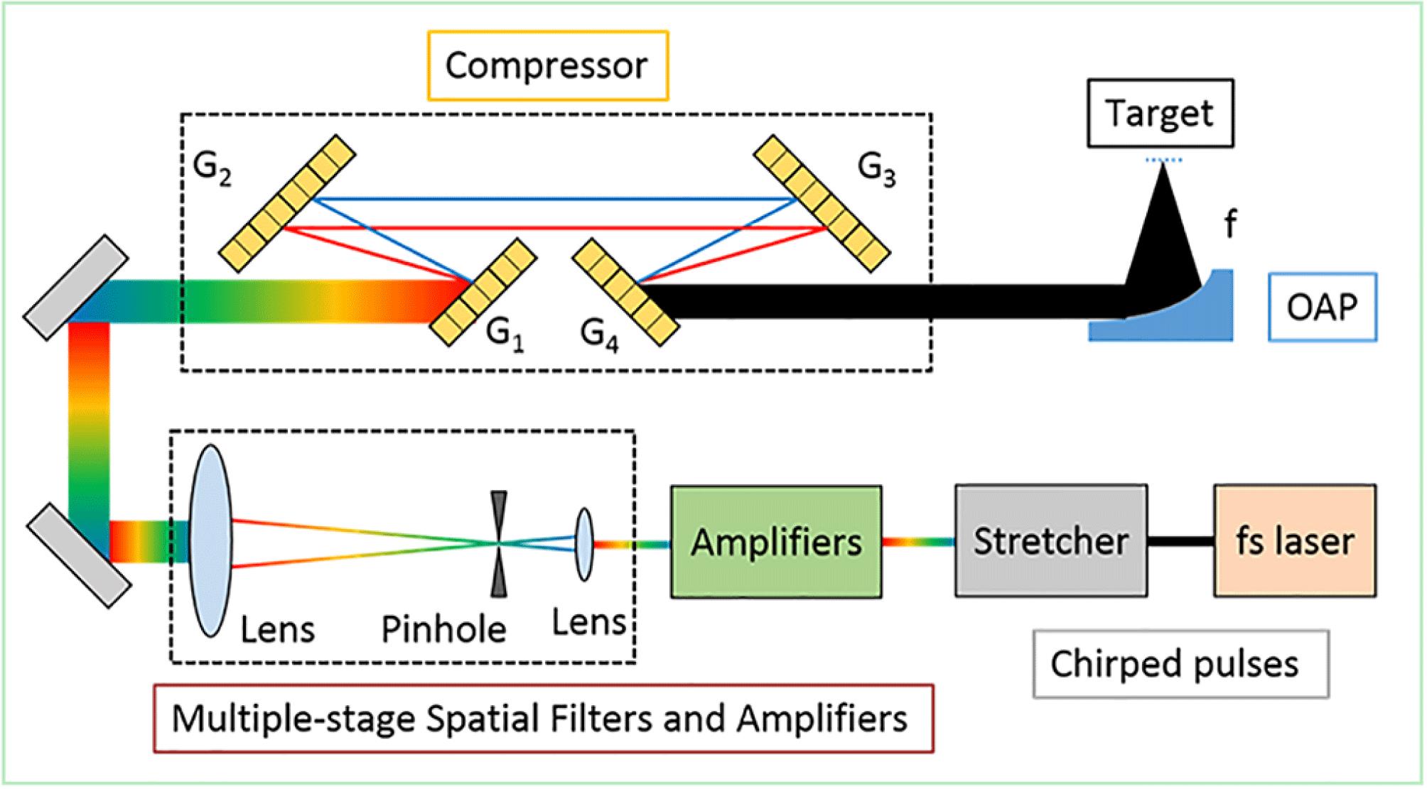
SG-II 5 PW high-power laser is located at National Laboratory on High Power Laser and Physics (NLHPLP) in Shanghai Institute of Optics and Fine Mechanics (SIOM). It is designed to be a multiple-stage OPCPA system working at the central wavelength of 808 nm, which will deliver an ultra-intense pulse with 150 J energy and 30 fs pulse width after compression at focal target region. The schematic of the SG-II 5 PW laser system is shown in Figure 1. A low-energy small-diameter chirped pulse is produced from an oscillator and a stretcher. The pulse gets amplified by multiple-stage amplifiers, based on OPCPA using LBO crystals. Meanwhile the pulse is propagated and expanded through multiple-stage spatial filters. Then the chirp of the high-energy large-aperture pulse is compensated in the four-grating compressor (G1–G4). Finally, the compressed high-power pulse is focused onto the target with ultrahigh intensity, utilizing an off-axis parabolic (OAP) mirror. Therefore, high temporal contrast at the focal region is required by physical experiments of laser–matter interaction.
The SF, not only works as a beam expander, but also filters out the high spatial frequency noise in the beam, improving the near-field beam quality and avoiding laser-induced damage to the optical elements in the laser system. The traditional spatial filter design is based on the configuration of two positive lenses (lens 1 and lens 2) and a pinhole, as shown in Figure 2. The pinhole is placed at the Fourier plane of the input lens (lens 1), passing the low frequency components and blocking the high-frequency components.
According to the image relaying requirement in SG-II 5 PW system, the multiple-stage lens-based spatial filters were designed with the parameters listed in Table 1. All the lenses used in the spatial filters are singlets. The input beam is expanded from 2.5-mm-diameter round shape to 290 mm $\times$ 290 mm square shape by 5-stage spatial filters (SF1–SF5). Because the large size LBO crystals and the gratings are square shape, between SF3 and SF4, the laser beam is spatially reshaped from round into square in order to make best use of these expensive elements of large aperture, which is achieved by using a 60 mm $\times$ 60 mm square pump light to amplify a 75-mm-diameter round signal light.
3.2 Chromatic aberration and radial group delay
However, unlike narrowband monochrome laser, the ultrashort pulse has a wide spectrum, whose spectral width is ${\sim}60$ nm in SG-II 5 PW system. In such large-aperture broadband laser system, the lens-based spatial filters will introduce chromatic aberration due to the dispersion in the material of lenses. The refractive index ($n$) varies at different wavelength ($\unicode[STIX]{x03BB}$), which makes the focal length ($f$) of the lens changes between wavelengths: $$\begin{eqnarray}f(\unicode[STIX]{x03BB})=\frac{1}{n(\unicode[STIX]{x03BB})-1}\frac{1}{\displaystyle \frac{1}{R_{1}}-\displaystyle \frac{1}{R_{2}}}=\frac{n(\unicode[STIX]{x03BB}_{0})-1}{n(\unicode[STIX]{x03BB})-1}f(\unicode[STIX]{x03BB}_{0}),\end{eqnarray}$$ where $R_{1}$, $R_{2}$ are the radii of curvature of the front and rear surfaces of a lens, respectively, and $\unicode[STIX]{x03BB}_{0}$ is the design wavelength, which is equal to the central wavelength of the pulse. Due to this reason, while the lens-based spatial filter operates perfectly at $\unicode[STIX]{x03BB}_{0}$ outputting a plane wave with a plane-wave input, the light at other wavelengths will experience chromatic aberration after passing through the lens-based spatial filter. The aberration is mainly defocus because of the focal length variation of the lenses related to wavelengths when the distance between the two lenses is fixed.
SF1
SF2
SF3
SF4
SF5
Size of input beam
$\unicode[STIX]{x1D719}2.5$
$\unicode[STIX]{x1D719}8.7$
$\unicode[STIX]{x1D719}20$
$60\times 60$
$145\times 145$
Focal length of lens 1
240
700
400
2480
2860
Focal length of lens 2
960
1930
1500
6000
5720
Size of output beam
$\unicode[STIX]{x1D719}10$
$\unicode[STIX]{x1D719}24$
$\unicode[STIX]{x1D719}75$
$145\times 145$
$290\times 290$
Table 1. Design of multiple-stage spatial filters in SG-II 5 PW system (unit: mm).
Using the matrix optics method, the curvature of the wave front at various wavelengths, $K(\unicode[STIX]{x03BB})$, can be calculated after going through the multiple-stage spatial filters in SG-II 5 PW system. The presence of curvature indicates the defocus of the wave front and the dispersion of such defocus can be represented by the slope of the wavelength-dependent curvature, $\text{d}K/\text{d}\unicode[STIX]{x03BB}$. As plotted in Figure 3, the curvature at central wavelength 808 nm is 0 (plane wave), while the curvatures at 778 nm and 838 nm are 0.426 km$^{-1}$ (convergent wave) and $-0.398~\text{km}^{-1}$ (divergent wave), respectively. The defocus dispersion curve (violet dashed line) tells that the relationship between wave front defocus and wavelength is nonlinear associated with the dispersion of the material of lenses. The defocus dispersion at 778 nm is $-14199$ m$^{-2}$ and the defocus dispersion at 838 nm is $-13278$ m$^{-2}$, yielding the average defocus dispersion is $-13721$ m$^{-2}$.
Although the central wavelength is free of chromatic aberration, RGD exists in the lens-based spatial filter for all the wavelengths. It is resulted from the positive lens, which is always thicker in the center and thinner on the edge. The light in different radial position $(r)$ will pass different length of the material and the light on the edge will lead the light in the center. The time between these two positions is called RGD or PTD[24]. The PTD of the multiple-stage spatial filters is equal to the sum of the PTDs of all the lenses, which can be written as below according to the previous literature[25]. $$\begin{eqnarray}\unicode[STIX]{x0394}T_{\text{SFs}}=\sum \unicode[STIX]{x0394}T_{\text{lens}}=\sum \frac{\mathop{r}_{0}^{2}-r^{2}}{2cf(\unicode[STIX]{x03BB})\left[n(\unicode[STIX]{x03BB})-1\right]}\left(-\unicode[STIX]{x03BB}\frac{\text{d}n}{\text{d}\unicode[STIX]{x03BB}}\right),\end{eqnarray}$$ where $c$ is the speed of light and $r_{0}$ is the radius of the laser beam. The PTD curves at various wavelengths (778 nm, 808 nm, and 838 nm) are plotted in Figure 4. The PTD at 778 nm is 401.2 fs, the PTD at 808 nm is 388.2 fs, and the PTD at 838 nm is 377.9 fs, giving that the shorter wavelength has a bit larger PTD in the multiple-stage spatial filters.
Therefore, the multiple-stage spatial filters introduce chromatic aberration and RGD into the ultrashort laser system and deliver a spatiotemporally coupled complex pulse with defocus dispersion and PTD.
3.3 Temporal contrast of the compressed and focused pulse
After coming out of the multiple-stage spatial filters, the pulse will go through the compressor and focused by OAP. We simulated the temporal contrast at the focal region with the influence of chromatic aberration and RGD caused by the multiple-stage lens-based spatial filters spatiotemporally coupled with compression and focusing. Four assumptions were made for this simulation: (1) the low-energy input is a temporally clean Fourier-transform-limited Gaussian pulse with spatially uniform beam profile; (2) the stretcher and compressor match with each other perfectly without any residual chirp or high order dispersion left after compression; (3) the amplifiers are so ideal and perfect that they introduce no modulation or noise to the pulse during amplification; (4) OAP focuses the pulse onto the target without any aberration or misalignment.
In the four-grating compressor, the groove density ($d$) of the diffractive gratings is 1740 lines/mm, the distance in the grating pair ($G$) is 712.3 mm, and the designed angle of incidence ($\unicode[STIX]{x1D6FE}$) is $56^{\circ }$. The grating equation is given by $$\begin{eqnarray}\sin \unicode[STIX]{x1D6FE}+\sin (\unicode[STIX]{x1D6FE}-\unicode[STIX]{x1D6FD})=\frac{m\unicode[STIX]{x03BB}}{d},\end{eqnarray}$$ where $\unicode[STIX]{x1D6FD}$ is the angle of diffraction and $m$ is the diffraction order. A schematic of a grating pair is shown in Figure 5(a) and $Y$ direction is perpendicular to the grooves of gratings. The phase change[26] introduced by one grating pair is: $$\begin{eqnarray}\unicode[STIX]{x0394}\unicode[STIX]{x1D711}=\frac{2\unicode[STIX]{x1D70B}G}{\unicode[STIX]{x03BB}\cos (\unicode[STIX]{x1D6FE}-\unicode[STIX]{x1D6FD})}(1+\cos \unicode[STIX]{x1D6FD})-\frac{2\unicode[STIX]{x1D70B}G}{d}\tan (\unicode[STIX]{x1D6FE}-\unicode[STIX]{x1D6FD}),\end{eqnarray}$$ where the first term is contributed by light path and the second term is the phase shift of the grating pair. The phase change of the four-grating compressor is the double of the phase change of a grating pair.
If the input light into the compressor is plane wave, the angles of incidence at all the positions are the same. But the light from the multiple-stage spatial filters suffers from chromatic aberration and the defocus dispersion makes the actual angle of incidence $\unicode[STIX]{x1D6FE}$ change with the different position and wavelength. Therefore the angle of diffraction $\unicode[STIX]{x1D6FD}$ and the phase change $\unicode[STIX]{x0394}\unicode[STIX]{x1D711}$ are depended on position and wavelength, resulting compression distortion and adding residual high order spatial dispersion into the output pulse. The residual dispersion curves at various spatial places are shown in Figure 5(b). The variate $y$ is the position in $Y$ direction, which is perpendicular to the grooves of gratings. The spectral phase change is directly relatedly to the angle change in $Y$ direction, and the angle change in $X$ direction does not play any role in the phase change of the compressor. The mount of residual dispersion is larger where the position is closer to the edge and only the central position has no dispersion.
With the assumptions mentioned above, the spatiotemporal pulse after compression can be expressed by[27, 28]$$\begin{eqnarray}\displaystyle & & \displaystyle E(x,y,t)=F^{-1}\{\tilde{E}(x,y,\unicode[STIX]{x03BB})\}=F^{-1}\left\{F\{E_{0}\}\exp \phantom{\frac{i\unicode[STIX]{x1D714}}{2c}}\right.\nonumber\\ \displaystyle & & \displaystyle \quad \left.\left[\frac{i\unicode[STIX]{x1D714}}{2c}K(\unicode[STIX]{x03BB})(x^{2}+y^{2})-i(\unicode[STIX]{x1D714}-\unicode[STIX]{x1D714}_{0})\unicode[STIX]{x0394}T_{\text{SFs}}-i2\unicode[STIX]{x1D6E5}\unicode[STIX]{x1D711}\right]\right\},\nonumber\\ \displaystyle & & \displaystyle\end{eqnarray}$$ where $E_{0}$ is the input pulse, the angular frequency $\unicode[STIX]{x1D714}=2\unicode[STIX]{x1D70B}/\unicode[STIX]{x03BB}$ and $\unicode[STIX]{x1D714}_{0}$ is the central angular frequency. $F$ is the Fourier transform between time $t$ and angular frequency $\unicode[STIX]{x1D714}$ and $F^{-1}$ is the corresponding inverse Fourier transform. The input pulse is spatially uniformed and not spatiotemporally coupled. Its spectrum and spectral phase are shown in Figure 6(a). The pulses at different spatial positions after compression are shown in Figure 6(b). The pulse in the central position remained high quality while the pulse on the edge position got stretchered and went ahead of that in the central position by 800 fs. The temporal contrast of the pulse on the edge position was degraded from $10^{20}$ to $10^{7}$. The spatial distribution of temporal contrast is shown in Figure 6(c). Thus, the large-aperture output pulse after compression is so complex that pulse distortion and temporal contrast degradation depend on spatial position.
The temporal contrast at the focal region is what we are interested in, since it determines the success of the physical experiments. Focusing of the complex spatiotemporal pulse described by Equation (5) was calculated with geometric-optical method under the OAP assumption we mentioned before. The results are shown in Figure 7. The black dashed line is the idea situation without any spatiotemporal distortions, no chromatic aberration or RGD, serving as a reference for comparison. The blue line is the actual situation with both chromatic aberration and RGD. There was an obvious gentle slope in the lead edge since 1 ps ahead of the peak and the temporal contrast dropped sharply from $10^{25}$ to $10^{7}$. The temporal profile at the focal region has an asymmetric long intensity tail. It is because the PTD of the spatial filters and residual dispersion of the compressor resulted from the chromatic aberration make the light on the edge get ahead of the light in the center and become the long tail after focusing. If we look into the two spatiotemporal distortions separately, the red line is only chromatic aberration (defocus) situation and the yellow line is only RGD (PTD) situation. Compared with the two lines, we can tell that RGD is responsible for the gentle slope in the lead edge while the chromatic aberration causes worse temporal contrast degradation.
Hence, we have proved that systematic spatiotemporal coupling in the high-power ultrashort laser could bring the final compressed and focused pulse a high noise level and a low steepness of the lead edge, causing temporal contrast degradation at the focal region. In order to obtain high temporal contrast pulse at the focal region in SG-II 5 PW laser system, chromatic aberration and RGD introduced by multiple-stage lens-based spatial filters should be compensated by additional compensation device or avoided by replacing lens-based spatial filters with mirror-based spatial filters in the further. If only the function of beam expanding is required and spatial filtering is not necessary, using achromatic beam expanders is a good option to minimize the chromatic aberration and PTD as well[29].
4 Conclusion
The success of physical experiments employing ultrashort petawatt lasers depends, to a great extent, on the temporal contrast at the focal region. We studied the spatiotemporal influences on temporal contrast in large-aperture broadband ultrashort petawatt lasers systematically. First, we reviewed the requirement of temporal contrast in physical experiments by the target damage mechanisms and summarized various causes of three general categories of noises, which are common in high-power ultrashort laser systems. Afterwards, we proved a system-wide spatiotemporal coupling to be one of the possible causes of temporal contrast degradation at the focal region. With a practical case of SG-II 5 PW large-aperture broadband ultrashort petawatt laser system, the influence of chromatic aberration and PTD introduced by lens-based spatial filters spatiotemporally coupled with compression and focusing on the temporal contrast of the compressed and focused pulse was simulated. Therefore, in order to obtain the anticipated laser–matter interaction results by petawatt lasers, more attention should be paid to the influence on temporal contrast at the focal region of the system-wide spatiotemporal coupling in the large-aperture broadband ultrashort lasers.
Ping Zhu, Xinglong Xie, Jun Kang, Qingwei Yang, Haidong Zhu, Ailin Guo, Meizhi Sun, Qi Gao, Ziruo Cui, Xiao Liang, Shunhua Yang, Dongjun Zhang, Jianqiang Zhu. Systematic study of spatiotemporal influences on temporal contrast in the focal region in large-aperture broadband ultrashort petawatt lasers[J]. High Power Laser Science and Engineering, 2018, 6(1): 010000e8