Metasurfaces have provided unprecedented degrees of freedom in manipulating electromagnetic waves upon interfaces. In this work, we first explore the condition of wide operating bandwidth in the view of reflective scheme, which indicates the necessity of anomalous dispersion. To this end, the leaky cavity modes (LCMs) in the meta-atom are analyzed and can make effective permittivity inversely proportional to frequency. Here we employ the longitudinal Fabry–Perot (F-P) resonances and transverse plasmonic resonances to improve the LCMs efficiency. It is shown that the order of F-P resonance can be customized by the plasmonic modes, that is, the F-P cavity propagation phase should match the phase delay of surface currents excited on the meta-atom. The th order F-P resonance will multiply the permittivity by a factor of , allowing larger phase accumulation with increasing frequencies and forming nonlinear phase distribution which can be applied in weak chromatic-aberration focusing design. As a proof-of-concept, we demonstrate a planar weak chromatic-aberration focusing reflector with a thickness of at 16.0–21.0 GHz. This work paves a robust way to advanced functional materials with anomalous dispersion and can be extended to higher frequencies such as terahertz, infrared, and optical frequencies.
1. INTRODUCTION
The meta-atom is the basis of metamaterial design; thereby the electromagnetic properties of the meta-atom determine the functional upper limit of the devices. In the past decades, metamaterial has progressed tremendously and gradually extended from microwave to acoustics, optics, and wider regions. In addition to deeper fields studies, people also tend to improve the functional properties of devices and promote operating efficiency. The working bandwidth has also experienced the development from narrowband to wideband. Initially, researchers designed many narrowband absorbers based on the strong loss at the anomalous dispersive point [1–4]. After that, wideband absorption of multi-point resonant superposition was also achieved [5–10]. In addition, the low-loss wideband devices were also reported a lot. In the optics region, different groups proposed some achromatic devices. The reported metalenses are operated over a continuous bandwidth in the visible by dispersion engineering of wavelength-dependent phase shifters [11–19]. But they still suffer from inefficiency due to loss which is related to Kramers–Kronig relations of permittivity [20–22]. The wide bandwidth always seems to be accompanied by larger loss and lower efficiency, which needs to be solved.
Different from previous studies that have balanced bandwidth and loss, in this work, we first explore the low-loss wideband condition in the view of the reflective scheme and obtain the wideband anomalous dispersion requirement. Then we find the leaky cavity modes (LCMs) make the permittivity inversely proportional to frequencies. To improve the efficiency of LCMs, we customize the transverse plasmonic mode to match with Fabry–Perot (F-P) resonance. In this way, the specific th resonance can be promoted to the main mode which can multiply the permittivity by a factor of , as is exhibited in Fig. 1. In this process, the LCMs which are enhanced enable larger phase accumulation, thereby forming a nonlinear phase distribution. As a proof of concept, we demonstrate an ultrathin weak chromatic-aberration focusing reflector (WCAFR) which has high-efficiency focusing above 80% from 16.0 to 21.0 GHz within thickness for right-handed circularly polarized (RHCP) incidence. The WCAFR is experimentally operated by the nonlinear phase distribution and still has focal diffraction phenomenon. But compared to the diffraction limits, its focal spots are mostly centered around the same location. Briefly, the proposed WCAFR might provide alternatives to fields of electromagnetic communication, antenna design, and radar imaging, etc. The concept can be readily extended to higher frequencies such as terahertz, infrared, and optical frequencies.
2. LOW-LOSS WIDE BANDWIDTH CONDITION FOR REFLECTIVE SCHEME
In principle, the standing wave model (SWM) can be used to explain most meta-atoms in the reflective scheme, which are composed of upper metallic patterns, dielectric substrates, and metal backgrounds. The illustrated parts objectively produce a cavity system and enable the incident wave to oscillate several times, which produces a standing wave.
Sign up for Photonics Research TOC. Get the latest issue of Photonics Research delivered right to you!Sign up now
Suppose that the incident wave , , propagates in the direction through medium 1 and strikes the boundary of medium 2 at [shown in Fig. 2(a)]. The reflected wave, returning in the direction, combines with incidence to yield the resulting field strength. By introducing the reflection coefficient at the boundary , we write the equation as [23]
is the propagation constant of the electromagnetic wave, and in other patterns, . is the phase factor, and is the real part attenuation coefficient of dielectric material. For the reflective meta-atom, the reflection coefficient . Considering the real field components of amplitude, Eq. (1) can be expressed as
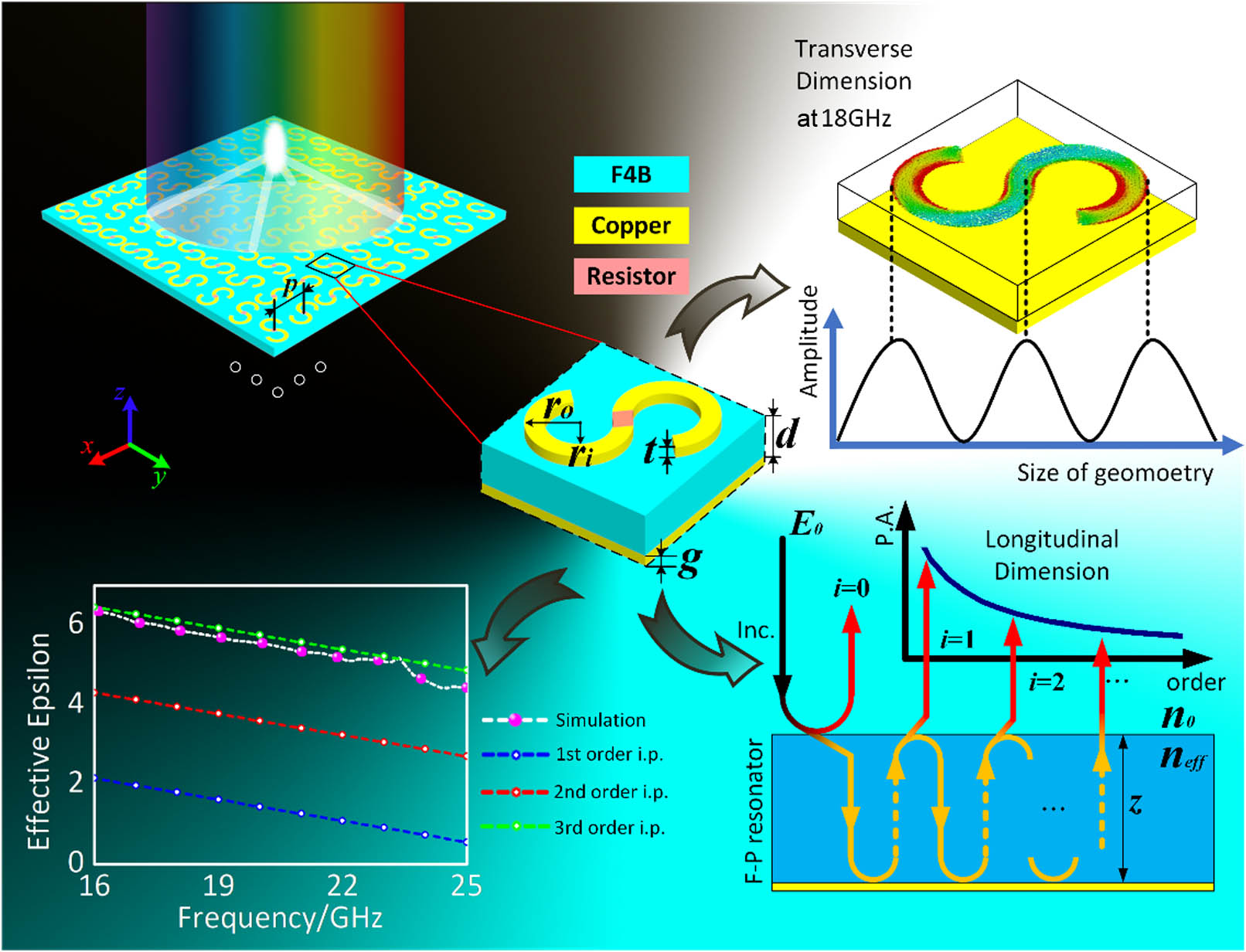
Replace the wavelength variable with frequency, and further make a transform as follows: where is the amplitude coefficient, . Taking the cavity thickness (z) as the independent variable and plugging the values into Eq. (3), the bandwidth upper boundary () and lower boundary () are shown in Fig. 2(b). The operating bandwidth under different cavity thicknesses can be worked out: . Figure 2(b) shows bandwidth limits under the fixed cavity thickness. The showed results indicate the trend as follows: in the reflective scheme, the wide operating band needs a thin thickness and higher operating frequencies. To obtain the wideband property, consider Eq. (3) and combine it with Eq. (4) [24]: where and are the real parts of permittivity and permeability of the dielectric, respectively. The and are tangent values of loss angle. The meta-atom is the nonmagnetic resonator; therefore, and . In Fig. 1, the effective epsilon curve gives the permittivity solutions of equation set under . The solutions are worked out considering the different order diffractions and thereby present the integer multiple relation. The results show a wideband anomalous dispersion trend where effective permittivity is inversely proportional to frequencies.
Figure 1.Schematic of coupling meta-atom and its realistic light deflection of WCAFR. All lights which have impact on the metasurface will deflect and intersect at the focal point. In the transverse dimension, the surface current distribution shows the order of the plasmonic mode on the meta-atom pattern. In the longitudinal dimension, there is a sketch map of diffraction mechanism and multiple reflections effect for reflective Fabry–Perot resonators. Every single unit can be regarded as an F-P resonator, inside which the wave oscillates back and forth times and is reflected as the th order output wave. (P.A., power amplitude.) The coupling between the transverse plasmonic mode and longitudinal F-P resonant mode enlarges the efficiency of LCMs, and further promotes the permittivity level. (i.p., ideal permittivity; the simulation results are obtained based on Appendix A. All dielectric material considered in derivations is F4B: .)
Figure 2.(a) Normal standing wave performance formed on the boundary between two media. (b) Ideal operating bandwidth of the reflective meta-atom [ means the consideration of most incident electromagnetic power (81%)]. The results are obtained based on Eq. (3). Here the common F4B is considered as the model dielectric material and its parameter is .
To further analyze the permittivity solutions, we make a comparison between the metallic dipole meta-atom and later designed wideband meta-atom. Figure 3 shows the dispersion trends and operating bandwidths of the two structures. The metallic dipole is the typical Lorentz model that has a narrow bandwidth [25]. At the resonant point, the electric susceptibility shows anomalous dispersive property with strong loss. The latter designed meta-atom has a wide bandwidth and wide anomalous dispersion in the operating band. The commonality between the two meta-atoms proves the conclusion of the above results.
Figure 3.(a) and (d) The normalized electric susceptibility of dipole under liner-polarization incidence and S-pattern under circular-polarization incidence (, ). (b) and (e) The performances of two meta-atoms with different operating bandwidths. Here the dipole is regarded as the transmissive type, so the transmission curve is the work band. The blue covered regions in (a) to (d) are the anomalous dispersive band. (c) and (f) show the different plasmonic modes on the meta-atoms.
In fact, the reflective cavity is not completely closed. Each round trip of the resonant wave through the cavity produces a partial leakage wave which is called leaky cavity modes in wave optics [26]. As shown in Fig. 1, the F-P resonance diagram, after the wave is incident on the F-P resonator, it will diffract with different orders and the trend presents a continuous and exponential decline due to dielectric loss. In this process, each order resonant wave escapes from the cavity with different efficiencies after passing through the dielectric interface. In the fixed thickness cavity, because the order of high-frequency diffracted wave is higher than that of low frequency, the high-order resonant mode increases the optical path of the corresponding order diffracted wave. That results in its loss also getting amplified times of the related order. Therefore, under the joint impact between the low-order diffraction in the low-frequency band and the high-order diffraction in high-frequency band, the LCMs get more severe with reducing wavelength so that they can make the F-P resonator show an anomalous dispersion trend.
To further analyze the coupling between the transverse plasmonic modes and longitudinal F-P resonances, we consider the high-order F-P diffraction within the meta-atom. As Fig. 1 shows, after the wave experiences a round trip in the cavity, it will produce a phase difference [26]:
Due to the specific F-P resonance having been promoted to the main mode, the th-order diffraction multiples the phase difference with the factor of . At the same time, we can plug the effective index of the meta-atom into Eq. (5) and write the phase distribution as Eq. (6): where the main mode order for the S-pattern meta-atom. The phase distribution of Eq. (6) can be regarded from LCMs, which allows larger phase accumulation with increasing frequencies. Also, in Appendix B, the meta-atom has the nonlinear phase in the transverse dimension that is related to spin-angle [Appendix B, Fig. 7(d)].
As a functional verification, we design a realistic ultrathin WCAFR with its architecture consisting of meta-atoms. The verified WCAFR with at the frequency is a regular diffractive reflector. Its phase profile was produced by the S-pattern meta-atom using the geometric phase for RHCP incidences. Its focal length is set as 100 mm, and the focal spot is located at the center of the section.
The WCAFR was simulated by CST Studio within open-add space along the and directions and with a plane wave as the incentive port in the axis. Experimentally, the focal lengths at different frequency points were obtained by measuring their intensity profiles along the propagation direction ( axis) in steps of 2 mm, as shown in Fig. 4. The coordinate corresponding to the peak intensity indicates the focal length for a given frequency point.
Figure 4.Performances of WCAFR. (a) Focal lengths and shifts of diffraction limits and WCAFR under different illuminated frequencies. (b) The calculated intensity distribution of diffraction limits in the xoy plane. (c), (d) Simulated and measured intensity distributions of WCAFR in the xoy interceptive plane. The incident wave frequencies are denoted on the top left corner. The incident direction is along the positive axis. (e) Normalized intensity profiles along the green dashed lines of (c). The green dashed lines pass through the center of focal spots in the case of . The white dashed frame parts are considered as the focal spot.
The former researchers preferred to divide the phase into basic phase and compensating phase [11,14]. Similarly, here we use the geometric phase as the basic one and the difference between the nonlinear and linear distribution impact as the compensating phase. (More details can be obtained in Appendix B [25,27–32].) Therefore, the proposed WCAFR cannot be completely achromatic, it is still slightly diffracted, and the focal point shifts back with increasing frequencies. But compared with the diffraction limits, its focal spots are almost centered around the same location.
We characterized the performance of the proposed WCAFR in terms of its focal length and focal spot profiles. They were measured at the focal plane under the RHCP incidence in an anechoic chamber. The normalized results show a weak trend of growing focal length as the frequencies increase but centering around 100 mm along the propagation axis within 10% error range. The spot profiles intercept the energy result () at to show itself. To further evaluate the ability of the WCAFR, focus efficiencies within its operating band are calculated in terms of the following equation [33]:
is the efficiency. and represent the reflection power and entire plane incident power, respectively. is the focus power. Here, the powers of the focal spot and total plane are integrated to obtain the power values. is the reflection coefficient of co-polarization under RHCP incidence. The efficiencies within 16.0 to 21.0 GHz are all over 80% (Fig. 5). Our design shows that the focal length shift of the WCAFR still presents a weak backward trend as the frequency increases, which objectively conforms to the traditional diffraction characteristic. Moreover, the proposed theory skillfully fits in the focusing theme and the planar WCAFR enables it to possibly achieve the weak chromatic aberration focusing across the microwave region from 16.0 to 21.0 GHz within the thickness.
Figure 5.Efficiencies of five observed frequency points.
All numerical simulations were performed using CST Studio. The WCAFR was settled with open-add space along the , , and directions and a plane wave was configured as the incentive port in the axis. The field monitors were utilized to obtain the near-field results.
All measurements were performed in a microwave anechoic chamber to avoid possible interference from the environment. The focal lengths at different frequency points were obtained by measuring their intensity profiles along the propagation direction ( axis) in steps of 2 mm, as shown in Fig. 9. The details can be garnered in Appendix C.
The parameters of the meta-atom are as follows: , , , , , and . The component materials include F4B: , ; copper: ; and resistor: . The meta-atom has a metallic ground plate with a thickness of 0.2 mm.
5. CONCLUSIONS
In summary, a low-loss wideband meta-atom is achieved both in theory and fabrication, which shows the necessity of wideband anomalous dispersion. In this process, we first obtained the anomalous dispersion condition through deriving the reflective meta-atom in the view of SWM. After that, to promote the efficiency of LCMs, we employed the high-order plasmonic mode to match with F-P resonance so that the high efficiency LCMs enable higher anomalous dispersive properties. At the same time, the promoted meta-atom enlarges a higher phase accumulation and therefore presents nonlinear phase distribution both in the longitudinal and transverse dimensions. As a functional verification, an ultrathin WCAFR was proposed, which has high-efficiency focusing above 80% from 16.0 to 21.0 GHz within thickness for RHCP incidences. Compared with diffraction limits, the nonlinear phase difference enables the focal spot centered around 100 mm. Briefly, the proposed weak chromatic aberration focusing devices might provide alternatives to fields of electromagnetic communication, antenna design, and radar imaging, etc. And the concept can be readily extended to higher frequencies such as terahertz, infrared, and optical frequencies.
APPENDIX A: METHOD TO OBTAIN THE EFFECTIVE PERMITTIVITY OF META-ATOM
For normal incidence of the reflective metasurface, the calculation and extraction of effective permittivity are difficult. That is because the available data can only be plugged into a set of equations and cannot get the unique solution. Here, we skillfully obtain the effective permittivity by considering the continuous cavity thickness variation, which can indicate the wavelength in the media.
For the convenience of extraction permittivity, we set a lumped resistor at the middle position of the meta-atom, which can only produce the absorption impact for left-handed circularly polarized (LHCP) incidence [34]. By changing the thickness of the cavity, the absorption for LHCP incidence presents periodic ups and downs.
In Fig. 6, the difference made under the thickness corresponding to the equal amplitude is the wavelength of the resonator cavity at the frequency. By comparing the wavelength of the vacuum with the wavelength of the simulation results, we can obtain the equivalent refractive index of the meta-atom:
Figure 6.Relations among the cavity thickness (), frequency, and absorption coefficient show the periodicity of SWM and it also provides an optimal solution to the cavity thickness .
Figure 7.(a) The phase for a WCAFR at arbitrary frequency of . (b) The achromatic phase mechanism scheme in our work. (The x coordinate is not 0 at the point where the axis intersects the axis.) (c) The nonlinear relation between the proportional coefficient and meta-atom position. (d) The phase distribution of the meta-atom.
It is known from the propagation of light in the medium that the cavity refractive index is equal to the wavelength of the wave vacuum divided by the wavelength in the cavity. Meantime, the nonmagnetic resonator has magnetic field insensitivity and thereby the effective permeability is 1 [25]. And the effective permittivity of the resonator can be worked out.
APPENDIX B: THE ACHROMATIC PHASE REQUIREMENT FOR WIDEBAND
Taking the case of the one-dimension focusing lens, the phase profiles can be written as where is the periodic length of the meta-atom, is the number of meta-atoms, and is the focal length of the metalens. In the situation where is much smaller than the operating wavelength, we expand the phase of meta-atom as a power series and plug it into Eq. (B1):
The achromatic condition for planar lens means that the focal length should have no relation to the frequency. Therefore, we should eliminate the effect of frequency variable on focal length in the above equation set. Considering these, the following conditions should be established:
As the previous research indicated [16,17], the achromatic metalens has to meet the wideband phase requirement so that it can produce a phase shifter to overcome chromatic limitation. In the above derivation, the phase of any meta-atom should be directly proportional to the frequency, and the coefficient presents a nonlinear increasing trend as the meta-atom is far from the central point. Therefore, the phase resonances of a well-designed meta-atom should perform anomalously as the nonlinear relation, which has been proved in previous reports [25,27–32]. The one-dimension phase profile scheme for wideband can be roughly played as Fig. 7(a). Figures 7(b) and 7(e) show the nonlinear relations with increasing frequencies and positions.
For the circular incidence scheme, we added a turning factor to the dipole model and made a further derivation. Supposing a light field that is normally incident on a dipole, the correctional drive equation is expressed as
But for the circular incidence scheme, the meta-atoms are always placed with different rotation angles to obtain the original phase. The phase is also called the Pancharatnam–Berry phase. Therefore, the above drive equation should be corrected with an angle (Fig. 8):
Figure 8.Circular incidence scheme for dipole with the rotation angle.
Figure 9.Near-field demonstration for the WCAFR metasurface. (a) Schematic of near-field measuring for the proposed WCAFR metasurface. (b) The surroundings and relevant details for the measuring experiment.
Thus, the equivalent electric polarizability is calculated as
The real part of is
The plasma frequency of metal is extremely high. Therefore, in the microwave band, [25], so the can be simplified as
And we can further obtain the effective permittivity:
The order of magnitude of item is much smaller than the previous item (). Hence, the effective refractive index and final phase expression can be listed:
The phase distribution of the proposed meta-atom also verifies the above derivation, and it is shown in Fig. 7(d).
APPENDIX C: THE DETAILS OF NUMERICAL SIMULATION AND EXPERIMENTALLY MEASURED CONDITIONS FOR THE VERIFIED METASURFACE
The FDTD numerical simulation results are shown in Figs. 4(b) and 4(d) and calculated by CST Microwave Studio. The electric fields results are obtained using the time domain solver under the open-add space along the , , and directions. A plane wave port is placed 200 mm far from the WCAFR metasurface and it can produce the RHCP excitation wave along the direction. We adopt the hexahedral mesh type with the 15 cells per wavelength to guarantee simulation accuracy. Five electric field monitors set at 16.13, 17.30, 18.50, 19.74, and 20.95 GHz are placed to present intensity distribution.
Experimentally, the verified metasurface is fabricated with the printed circuit board process and measured in the anechoic chamber. We place a circular polarization horn antenna as the excitation port but with enough setup distance (1 m) to guarantee the equivalent plane wave. The near-field data are collected through scanning the region by probe. Restricted by the experimental conditions, we only scan a limited region of which is enough to present the WCAFR metasurface’s wideband focusing ability. In the paper, we have reduced the shown area of the result so that the short edge has the same width as the metasurface edge. In the process of scanning the region to collect data, we set the probe to move at a step of 3 mm in the direction and 2 mm in the direction.
For near-field simulation, the FDTD is chosen here, which can provide an intrinsically fast speed, and the CST Microwave Studio, which is much easier to operate than other software.
[10] R. Kumar, B. K. Singh, R. K. Tiwari, P. C. Pandey. Perfect selective metamaterial absorber with thin-film of GaAs layer in the visible region for solar cell applications. Opt. Quantum Electron., 54, 416(2021).