
Hua-Mei Li, Peng-Fei Hou, Jin-Bin Wang, Hong-Jia Song, Xiang-Li Zhong. Single-event-upset effect simulation of HfO2-based ferroelectric field effect transistor read and write circuits [J]. Acta Physica Sinica, 2020, 69(9): 098502-1
- Acta Physica Sinica
- Vol. 69, Issue 9, 098502-1 (2020)
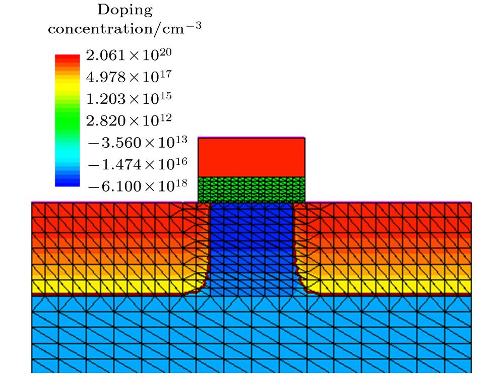
Fig. 1. Device physical models of HfO2-based FeFET.
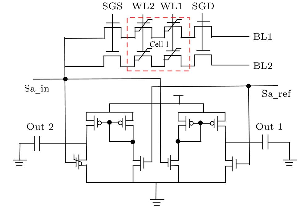
Fig. 2. Read and write circuit of 2 × 2 ferroelectric memory array.
Fig. 3. Control simulation timing of 2 × 2 ferroelectric memory array.
Fig. 4. Charge density distribution inside the device when HfO2-based FeFET is written: (a) The internal charge distribution of the device is written with “1”; (b) the internal charge distribution of the device is written with “0”.
Fig. 5. Reading and writing of ferroelectric memory arrays: (a) Changes in the output signal of the sense amplifier; (b) changes in the output signal of cell 1; (c) changes in the polarization of cell 1.
Fig. 6. Transient effects of single-particle incident read and write “0” ferroelectric storage tube drain: (a) Change of drain current pulse; (b) change of cell 1 output signal; (c) change of cell 1 polarization intensity; (d) change of sense amplifier output signal.
Fig. 7. Transient effects of single-particle incident read and write “1” ferroelectric storage tube drain: (a) Change of cell 1 polarization intensity; (b) change of cell 1 output signal; (c) change of sense amplifier output signal.
Fig. 8. Transient effects of a single-particle incident sensible amplifier input tube when reading and writing “0”: (a) Change of ferroelectric cell 1 polarization intensity; (b) change of sense amplifier output signal.
Fig. 9. Transient effects of a single-particle incident sensible amplifier input tube when reading and writing “1”: (a) Change of ferroelectric transistor polarization intensity; (b) change of sense amplifier output signal.
Fig. 10. Signal change of ferroelectric memory cell cell 1 under single-particle HZO ferroelectric thin film with different remanent polarization and coercive field: (a) Change of ferroelectric transistor polarization intensity; (b) change of sense amplifier output signal.
Fig. 11. Transient effects of two single-particle incident read and write “1” ferroelectric storage tube drain: (a) Change of drain current pulse; (b) change of cell 1 polarization intensity; (c) change of sense amplifier output signal.
Fig. 12. Transient effects of two single-particle incident read and write “0” ferroelectric storage tube drain: (a) Change of cell 1 polarization intensity; (b) change of sense amplifier output signal.
|
Table 1. Process parameters of HfO2-FeFET.
| |||||||||||||||||||||||
Table 2.
Voltage difference change between Out 1 and Out 2.
输出端Out 1和Out 2之间的电位差变化

Set citation alerts for the article
Please enter your email address
© Copyright 2018-2021 | Chinese Laser Press. All Rights Reserved 沪ICP备15018463号-20