
Shaoshuo Mu, Chuan Qiao. Ground-Target Geo-Location Method Based on Extended Kalman Filtering for Small-Scale Airborne Electro-Optical Platform[J]. Acta Optica Sinica, 2019, 39(5): 0528001
- Acta Optica Sinica
- Vol. 39, Issue 5, 0528001 (2019)
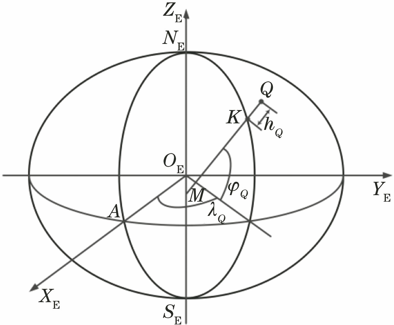
Fig. 1. ECEF coordinate system
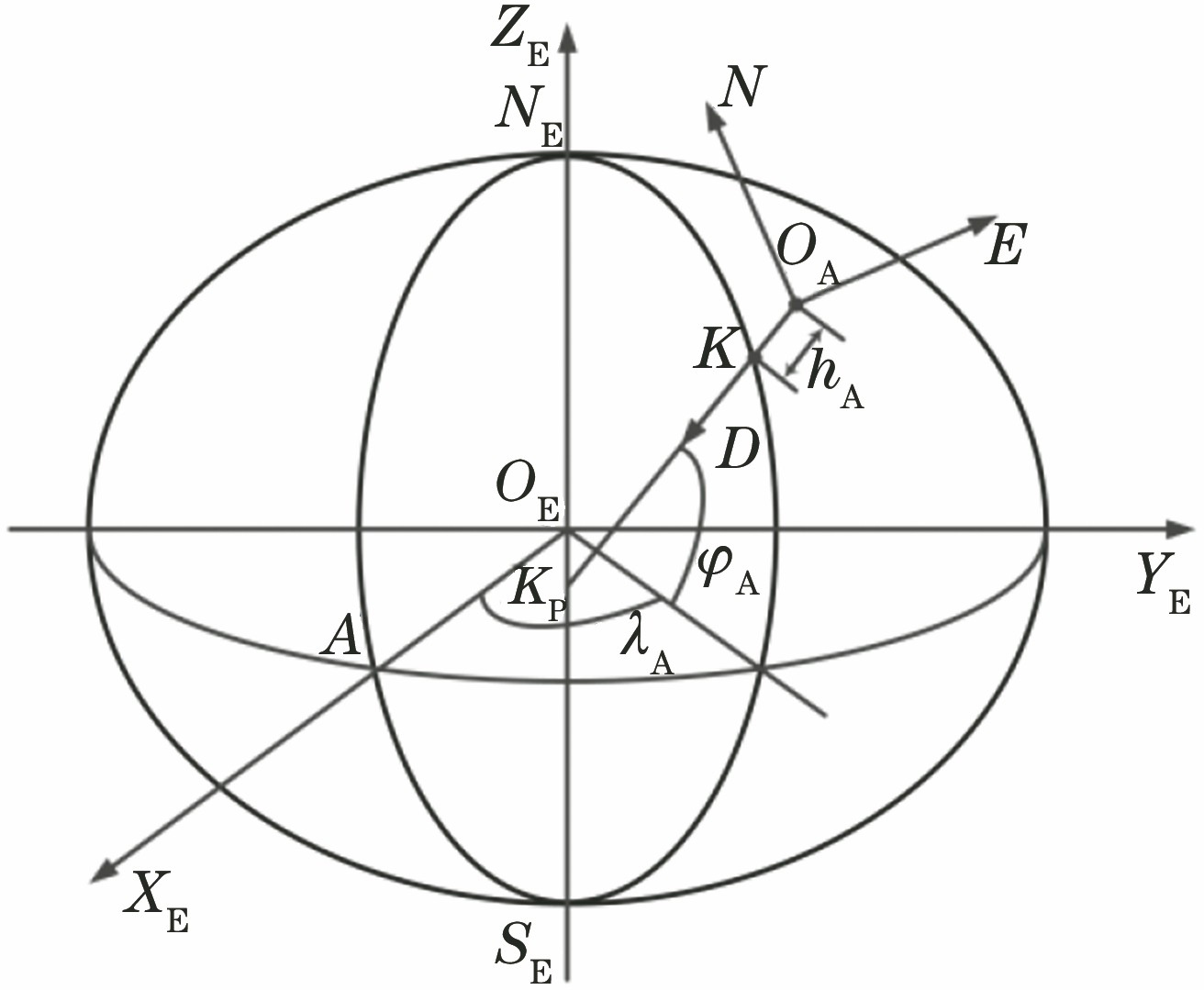
Fig. 2. ECEF coordinate and NED coordinate sysems
Fig. 3. NED and AC coordinate systems
Fig. 4. Structural diagram of airborne electro-optical platform
Fig. 5. Schematic of target projection on detector
Fig. 6. Flow chart of extended Kalman filtering
Fig. 7. Flight path and measurement points in simulation
Fig. 8. Simulation test. (a) Geo-location results; (b) geo-location errors
Fig. 9. Influence of initial position guess on target geo-location accuracy
Fig. 10. Influence of flight path on target geo-location accuracy. (a) Flight paths; (b) target geo-location error under different flight paths
Fig. 11. Influence of error parameter on target geo-location accuracy. (a) Position error; (b) line of sight direction error
Fig. 12. Flight test. (a) Small-scale airborne electro-optical platform; (b) flight path
Fig. 13. Flight test. (a) Geo-location results; (b) geo-location errors
| |||||||||||||||||||||||||||||||||
Table 1. Error parameters in simulation

Set citation alerts for the article
Please enter your email address
© Copyright 2018-2021 | Chinese Laser Press. All Rights Reserved 沪ICP备15018463号-20