
Yuandong Li, Rong Wang, Tao Pu, Huatao Zhu, Jilin Zheng, Meng Hu. Review on High Out-of-Band Suppression Ratio of Microwave Photonic Filter[J]. Laser & Optoelectronics Progress, 2018, 55(2): 020005
- Laser & Optoelectronics Progress
- Vol. 55, Issue 2, 020005 (2018)
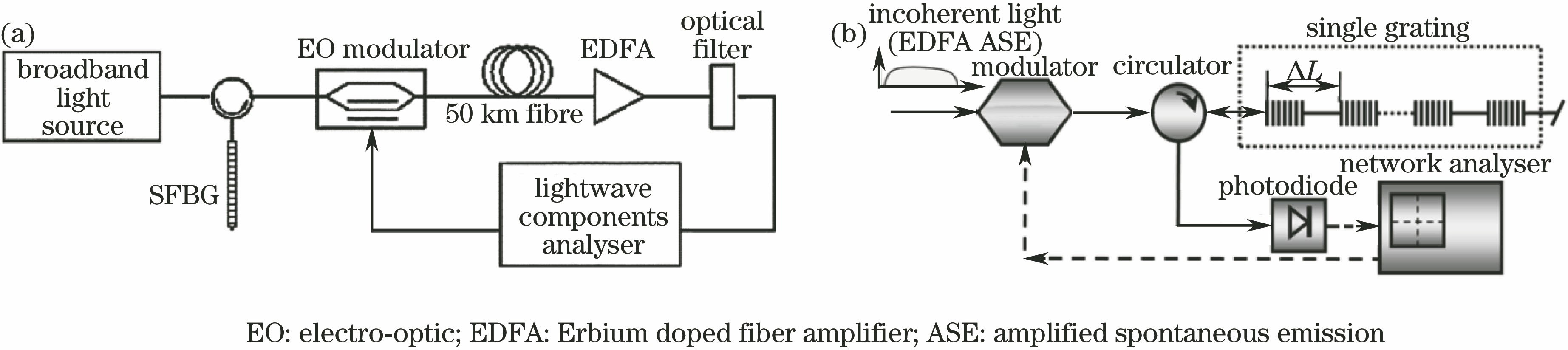
Fig. 1. Schematic illustrations of high out-of-band suppression ratio FIR MPF using SFBG and Gaussian window function with (a) 24 taps and (b) 18 taps
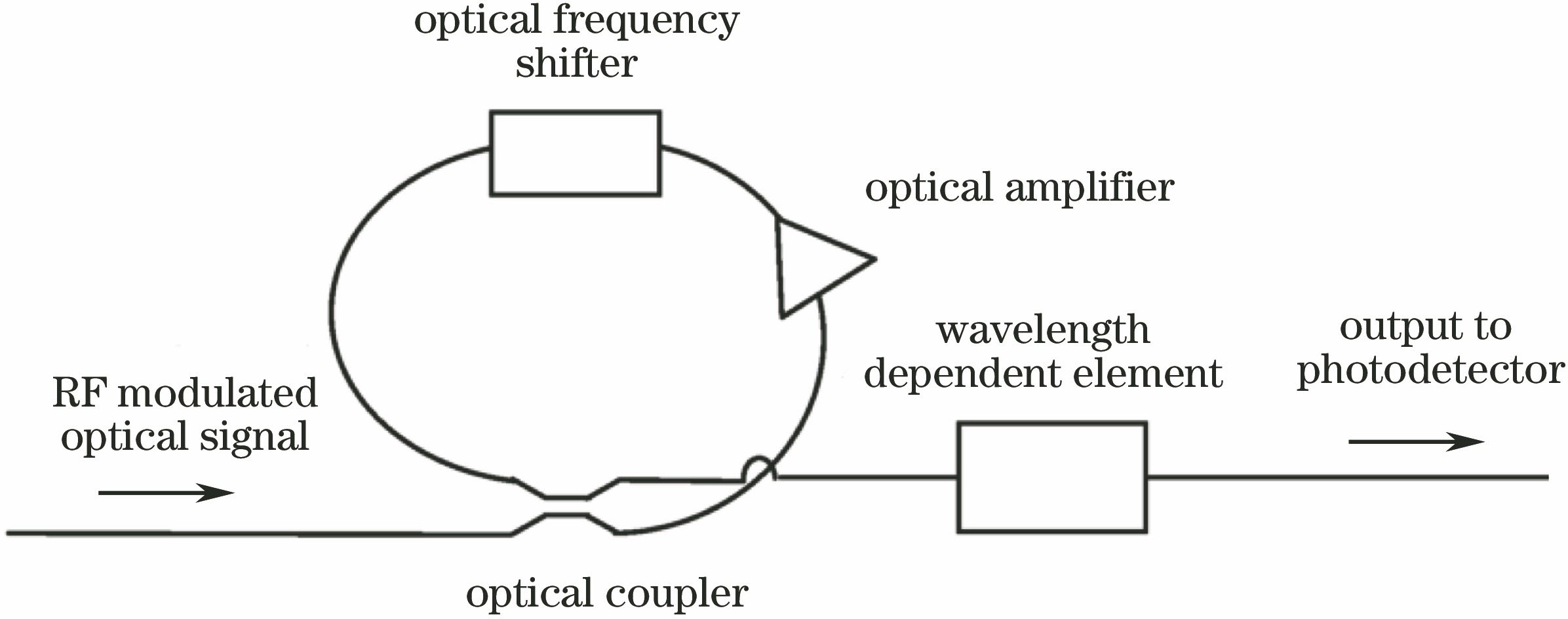
Fig. 2. Schematic illustration of the high out-of-band suppression ratio FIR MPF using Sagnac loop and Kaiser window function
Fig. 3. (a) Schematic illustration of the high out-of-band suppression ratio FIR MPF using the Gaussian apodized broadband combs; (b) depiction of the cascaded FWM process
Fig. 4. Schematic illustrations of the 3rd IIR MPF based on the interference effect between the compositions of the tap
Fig. 5. Four schematic illustrations of cascade configurations of high order IIR MPF
Fig. 6. Schematic illustrations of high out-of-band suppression ratio single bandpass MPF using subtractive in (a) electric and (b) optical domains
Fig. 7. Schematic illustration of high out-of-band suppression ratio single bandpass MPF using modified subtraction in optical domain
Fig. 8. Schematic illustration of high out-of-band suppression ratio single bandpass MPF using (a) passive Lyot optical filter and (b) active optical SBS gain spectrum filter based on spectrum mapping approaches
Fig. 9. Three schemes of notch MPF and theory of notch depth
Fig. 10. (a) Schematic illustration of on-off between bandpass and notch MPFs; (b) spectral respons of the notch MPF; (c) spectral response of bandpass MPF
Fig. 11. (a) Schematic illustration of a single bandpass MPF based on carrier-suppressed single sideband injected DFB laser and (b) spectral responses under different detuning frequencies

Set citation alerts for the article
Please enter your email address
© Copyright 2018-2021 | Chinese Laser Press. All Rights Reserved 沪ICP备15018463号-20