
Jiachen Yu, Pingjun Wang, Qi Yu, Yin Zhang, Wei Xiong, Xuzong Chen, "Stabilized DFB laser system with large tuning range," Chin. Opt. Lett. 16, 031403 (2018)
- Chinese Optics Letters
- Vol. 16, Issue 3, 031403 (2018)
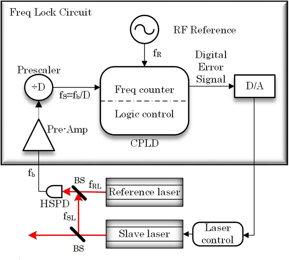
Fig. 1. Structure of the laser system. Beams from two lasers with frequencies f RL f SL f b D f S = f b / D
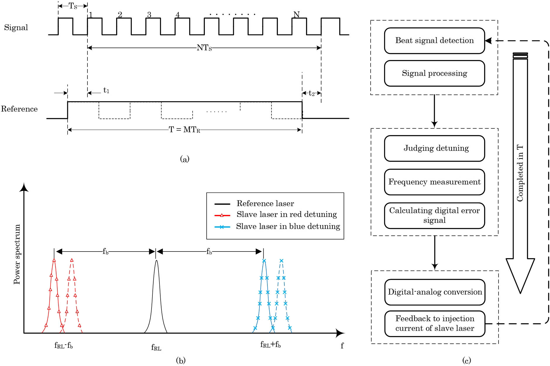
Fig. 2. Principle of the system. (a) Pulse-counting method used for frequency measurement. (b) Method we use to judge frequency polarity of the slave laser. (c) Working process of the entire system.
Fig. 3. Frequency distribution of the DBS when free running and locked (a) span = 100 kHz span = 1 kHz
Fig. 4. Allan deviation of the beating signal for free running (blue dash line) and locked (red solid line) conditions.


Set citation alerts for the article
Please enter your email address

© Copyright 2018-2021 | Chinese Laser Press. All Rights Reserved 沪ICP备15018463号-20