We propose, design, and realize a compact stabilized laser system that can be tuned within 24 GHz automatically. This laser system consists of two distributed feedback (DFB) lasers, one of which is reference and locked to the D2 line of , the other laser is a slave that is locked to the reference laser via a loop servo. We measured the frequency of the beating signal of the two lasers and generated an error signal, which controlled the frequency of the slave laser to close the loop. We compressed the fluctuation of the beating signal’s frequency to less than 1 MHz. Furthermore, the system can also automatically determine and control whether the slave is red detuned or blue detuned to the reference. The dimensions of our laser system are about . This kind of laser system can be applied in many important applications, such as atomic interferometer and cold atomic clock.
Stabilized lasers with a large tuning range are major facilities in fundamental physical experiments and state-of-the-art precision measurement applications. For instance, in experiments of ultra-cold atoms[1–4], lasers are applied to cooling and manipulating atoms. In a gyroscope[5,6], gravimeter[7,8], and other instruments related to atoms[9–11], lasers play a significant role in controlling and detection. It is really a challenge to acquire a stabilized laser with a large tuning range. Many solutions have been developed to achieve the purpose, such as an acousto-optic modulator[12] (AOM), electro-optic modulator[13] (EOM), and optically phase locked loop[14,15] (OPLL). With AOMs, we can obtain space-separated lasers with different frequencies. However, the bandwidths of AOMs are much less than their operation frequencies. By means of an EOM, the carrier and side-band lasers overlap in space. An OPLL, in another aspect, is not able to achieve a large dynamic range and high precision simultaneously.
In this Letter, we propose a frequency lock method to achieve a wide tuning range. In our system, there are two lasers: one is the reference, which is locked through saturated absorption spectroscopy, and the other is the slave, which is locked to the reference. With this method, lasers can be tuned without sacrificing precision in 24 GHz, which is much larger than previous work on OPLL, the dynamic range of which is about several gigahertz (GHz). Moreover, our method can judge and control detuning polarity of the slave laser automatically, which makes it possible to achieve complete automatic frequency lock. This is a major advantage of our method compared to the existing OPLL method.
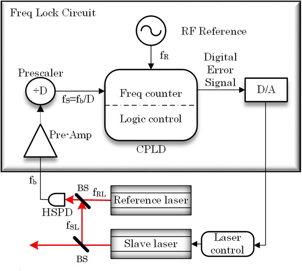
The layout of our system is shown in Fig. 1. Beams from the reference laser and the slave laser are combined together and then detected using a high-speed photo detector (HSPD). The beating signal generated by the HSPD is then sent to the frequency lock component to generate the error signal. Afterwards, the error signal is applied to modulating the frequency of the slave laser to close the loop.
Sign up for Chinese Optics Letters TOC. Get the latest issue of Chinese Optics Letters delivered right to you!Sign up now
Figure 1.Structure of the laser system. Beams from two lasers with frequencies and are combined through two beam splitters (BS), and the beating signal, whose frequency is , is detected by a high-speed photo detector (HSPD). Afterwards, the beating signal is amplified and divided (division ratio is marked as ), and the divided beating signal (DBS) with a frequency is generated. Taking a rubidium clock as the RF reference, the frequency counter measures the frequency of DBS and compares it with the expected frequency we set. Afterwards, a digital error signal is generated by the logic control and converted into analog by a digital-to-analog converter (DAC). Finally, this analog signal is applied to modulating the frequency of slave laser.
The frequency lock component contains a complex programmable logic device (CPLD) chip, which is designed as a frequency counter and logic control. A pre-scaler is employed to decrease the frequency of the beating signal by times, so that the frequency counter is able to measure it.
A rubidium clock worked as the RF reference, which provided a time and frequency standard for the frequency counter. As long as the counter obtained the frequency in digits, the logic control module calculates the difference between the measured frequency and the expected one we set; afterwards, a digital error signal is generated. Finally, a digital-to-analog converter (DAC) will convert the digital error signal into an analog one and feed it back to control the slave laser.
In our design, the frequency counter is realized by means of the pulse-counting method. The principle of this method is illustrated in Fig. 2(a). The gate time is obtained by counting periods of the reference signal, of which the frequency is . During the gate time, the counter records the oscillating times of the divided beating signal (DBS), of which the frequency is . Then, we can figure out that . The meaning of , is shown in Fig. 2(a). We can see that , and . Therefore, we have where , . The measured value of , marked as , should be then, we have the beating signal frequency , where represents the division ratio of the pre-scaler.
Figure 2.Principle of the system. (a) Pulse-counting method used for frequency measurement. (b) Method we use to judge frequency polarity of the slave laser. (c) Working process of the entire system.
On the other hand, the uncertainty of not only comes from the error in , but also is introduced by the uncertainty of the reference frequency. The uncertainty of measured frequency is corrected as and the maximum measurement error of is revised as
As shown in Eq. (4), the error consists of three terms: the first one originates from the error of the pulses’ counting; the other two terms are both related to the fluctuation of reference frequency. The second term is usually much less than the first term, since is usually in the order of for a rubidium clock. The third term may be in the same order as the first one, if is in the order of .
Our system is also able to automatically judge and control whether the slave laser is red detuned or blue detuned to the reference. The detuning polarity cannot be judged even if the frequency of the beating signal is measured. We propose a method to solve the problem, as shown in Fig. 2(b). The frequency of the reference laser is noted as , which is fixed in the system. The frequency of the beating signal is , which can be measured. As a result, the frequency of the slave laser is either (triangle marked red line) or (cross marked blue line). Afterwards, we change the frequency of the slave laser by a certain value with a tuning to the injection current. For instance, we increase the frequency of the slave laser slightly (from a solid line to a dash line). We then update the frequency of the beating signal. As shown in the figure, if the slave laser is in red detuned, the frequency of the beating signal will decrease. Otherwise, if the slave laser is in blue detuned, the frequency will increase.
The work flow of our system is shown in Fig. 2(c). Firstly, the beating signal is detected by the HSPD and amplified and pre-scaled for frequency measurement. Secondly, the frequency counter and the logic controller will automatically judge the detuning polarity of the slave laser and then generate the digital error signal according to the frequency measurement and the set point. Finally, a DAC will convert the digital error signal to an analogue one, and then the analogue error signal is sent to adjust the driving current of the slave laser to lock the frequency of the slave laser. During a single process of feedback, the time (the gate time ) frequency detection takes is much more than the time of generating and feeding the error signal, so the loop delay mainly depends on gate time .
The system performances mainly include dynamic range, minimum tuning step, and precision. The dynamic range of our laser system is related to the responding bandwidth of the HSPD, the working bandwidth of the pre-amplifier and pre-scaler, and the slave laser’s tuning range, which is represented as , where is the dynamic range of DAC’s output, and represents the voltage tuning ratio of the slave laser. The minimum of the three characteristics above determines the maximum dynamic range of the whole system.
The precision of our system depends on the accuracy of the frequency measurement, the noise of the DAC output, and the phase noise of the HSPD. As shown in Eq. (4), the precision introduced by the accuracy of the frequency measurement is expected to be
On the other hand, the noise of the DAC output leads to the uncertainty as , where is the noise of the DAC. The comprehensive accuracy mainly comes from the two parts.
The minimum tuning step is mainly related to two factors, one of which is the DAC’s integral nonlinearity , leading to . The other one is the precision of the measurement. The minimum tuning step is the synthesis of the two factors above.
In our system, the HSPD detecting the beating signal can respond as high as 12 GHz. The pre-amplifier and pre-scaler both can work at 12 GHz. Consequently, the system can work at 12 GHz. The DAC we choose has a resolution of 18 bits and output. The voltage tuning ratio of the slave laser is . Therefore, the tuning range of the slave laser reaches . As a result, the dynamic range of our laser system is .
The division ratio of the pre-scaler is . We set the gate time as 1 ms. The reference we use is a rubidium clock with the uncertainty better than . For the dynamic range of , the maximum frequency of is 37.5 MHz. Therefore, the maximum counting number is about 37,500. We have , according to the parameters above. Derived from Eq. (5), precision induced by the frequency measurement is . Moreover, the noise of the DAC output is measured to be less than 20 μV, which results in an uncertainty as . The latter uncertainty is negligible compared with the one introduced by the frequency measurement. The phase noise of the HSPD is evaluated by detecting the beating signal of two laser beams from the same laser diode; one of the beams is shifted by an AOM. In this condition, the bandwidth of the beating signal is mainly introduced by the phase noise of the laser, the AOM driver, and the HSPD. The linewidth of the beating signal is measured to be less than 1 Hz. Therefore, the uncertainty introduced by the HSPD can be neglected in our work. Consequently, locking precision of our system is expected to be 640 kHz.
According to the DAC’s parameter given above, the tuning step caused by the DAC is , which is much less than precision of the system. Thus, the minimum tuning step is about 640 kHz.
In our experiment, the reference and slave laser are distributed feedback (DFB) lasers with linewidths of about 4 MHz. The temperature tuning ratio is about , and the temperature of the lasers is stabilized with an uncertainty better than 69 μK at 1 h. The current tuning ratio of the lasers is claimed to be , and the measured result is about . The reference laser is locked to D2b line hyperfine spectra of by means of a saturated absorption spectrum (SAS)[16]. The stability of the reference laser with an average time of 100 s is . We set the detuning of the slave laser to a red detuned 3.2 GHz. The DBS frequency from the pre-scaler is expected to be 10 MHz. It is known that, in the premise of stabilization of the servo loop, increasing the gain of the loop can improve the lock performance of the system[17,18]. Therefore, we optimize the loop gain to critical damping to obtain high stability and short locking time simultaneously without oscillation. We applied another precision frequency counter to measure the frequency of with the servo loop open and closed for an hour separately. The frequency fluctuated in a range, and we separated the whole distribution range into 50 subintervals and recorded the number of data in each subinterval. Frequency distributions under the two conditions above are plotted and shown in Fig. 3(a), and the Y axis represents the relative number of data in each subinterval. It can be obviously seen that with an open servo loop, the frequency lies within the range of about 100 kHz. When the loop is closed, the frequency is stabilized. The fluctuation of the frequency is notably compressed. Fig. 3(b) shows the frequency distribution of within the 1 kHz span when the servo loop is closed. As shown in the figure, the fluctuation of is compressed to around 0.3 kHz when the loop is closed. Correspondingly, the fluctuation of the beating signal frequency is compressed from 12.8 MHz (free running slave laser) to 96 kHz by about 133 times.
Figure 3.Frequency distribution of the DBS when free running and locked (a) , (b) .
The stability of the beating signal is evaluated by means of Allan deviation[19], and the result is shown in Fig. 4. The dash line represents stability when the system is free running, and the solid line represents stability of the beating signal when it is locked. In our system, the 1 s stability, as shown in the figure, is improved from to . The stability with an averaging time of 100 s can reach .
Figure 4.Allan deviation of the beating signal for free running (blue dash line) and locked (red solid line) conditions.
Data acquisition lasts for about 3 h, during which the change of the environment temperature was measured to be 5°C. The maximum drift of the laser diode temperature was also recorded and was less than 1 mK. Under these conditions, our laser system maintained the locking. Taking advantage of the mechanical design of our system, the locking performance is not sensitive to vibration.
In conclusion, we design and accomplish a stabilized laser system, which can be tuned within up to 24 GHz and, moreover, can judge detuning polarity of a laser automatically. The system dimensions remarkably decrease compared to common commercial laser systems. The stability of the beating signal can be improved to be average. Our system is appropriate for applications in portable instruments involving cold atoms.
[5] W. Liang, V. Ilchenko, D. Eliyahu, A. Savchenkov, A. Matsko, L. Maleki. 2017 IEEE International Symposium on Inertial Sensors and Systems (INERTIAL), 8(2017).