
J. Goodman, M. King, E. J. Dolier, R. Wilson, R. J. Gray, P. McKenna, "Optimization and control of synchrotron emission in ultraintense laser–solid interactions using machine learning," High Power Laser Sci. Eng. 11, 03000e34 (2023)
- High Power Laser Science and Engineering
- Vol. 11, Issue 3, 03000e34 (2023)
Abstract
1 Introduction
Irradiation of a solid target with a relativistically intense laser pulse typically produces a large number of photons with energies extending to the multi-MeV range, due to bremsstrahlung radiation from laser-accelerated electrons propagating through the target[1–3] and X-ray line emission from excited atomic states[4]. These bright sources of X-rays and gamma rays have potential applications including radiography[5–8], initiating photonuclear reactions[1,9] and producing beams of positrons through the Bethe–Heitler process[10–14]. New multi-PW laser systems offer increased achievable peak laser intensities of approximately
1.1 Gamma ray generation
The energy electrons can gain in a high-intensity laser field scaling with the parameter
All-optical demonstrations of radiation reaction with much lower laser intensities have been performed[22,23] in which a laser wakefield accelerated electron beam was collided with a laser pulse. Although higher laser intensities are required for the synchrotron radiation to become measurable in laser–solid interactions, theoretical and numerical studies indicate the generation of a high-power gamma ray flash with of the order of
Sign up for High Power Laser Science and Engineering TOC. Get the latest issue of High Power Laser Science and Engineering delivered right to you!Sign up now
1.2 Transparency
When an ultrathin foil is irradiated by a high-power laser pulse, the combined expansion of the target and heating of the electrons to relativistic velocities can reduce the plasma frequency (
1.3 Optimization
There are many other parameters that can influence the generation of synchrotron radiation in these interactions, and finding the optimum conditions over a parameter search space with a large number of dimensions would be extremely costly and time consuming to achieve manually. In recent years, it has become possible to apply machine learning-based techniques as an efficient method of searching this multi-dimensional parameter space to find input conditions for the desired source parameters. Bayesian optimization[63,64] is one such technique that is useful when the objective function chosen to be optimized, such as the yield of gamma rays, is susceptible to noise and is costly to evaluate. This approach has already been demonstrated to improve electron and X-ray beams from wakefield accelerators[65,66] and laser-driven proton acceleration in simulations[67]. Other machine learning techniques that have been applied in the study of laser–plasma accelerators include neural networks[68,69] and evolutionary algorithms[70–73].
1.4 Multiple objectives
The beam of high-energy particles or photons generated in these interactions is defined by many properties, such as the conversion efficiency, energy spectrum and divergence. For some applications, it is necessary to achieve several beam properties within a specific range and thus tune a number of the beam properties simultaneously. Often in such a scenario, these properties are individually optimized in different regions of the search space. Multi-objective optimization[74–77] involves finding a finite set of solutions that are located on the optimum edges of the objective space, known as the Pareto front, where one of the objectives cannot be improved without a trade-off in another. However, if only a single solution is desired, such as in the case of an automated laser-driven particle or radiation source guided by machine learning, it is not necessary to find a large set of solutions to choose between, and the problem can be reduced to the optimization of a single objective function; although, this presents the challenge of combining the multiple objectives into a single composite function that is optimized at the most desirable location on the unknown Pareto front. Experimental optimization of laser–plasma accelerated electrons has been demonstrated with such a function incorporating multiple electron beam properties[65] and, in a simulation-based study[77], different functions based on the same physical properties are demonstrated to optimize at different locations on the Pareto front found using multi-objective optimization.
In this paper, a numerical investigation, facilitated by the application of machine learning-based optimization, of the production of high-energy photons in the interaction of an ultraintense laser pulse with a thin solid foil is reported. In a number of 2D parameter space scans, using the BISHOP code[67], the target foil thickness, the angle-of-incidence of the laser pulse and the laser pulse duration, focal spot size, defocus and peak intensity are varied to show the effect on the photon emission for p-polarized laser light (Section 3). For constant laser pulse energy, the conversion efficiency to synchrotron radiation is highest for parameters that maximize the peak laser intensity incident on the target surface, and oblique incidence provides a
2 Methodology
The fully relativistic particle-in-cell (PIC) code EPOCH[78] was used in two and three dimensions to model the gamma ray generation in the interaction. Output data were generated individually for synchrotron and bremsstrahlung photons above 100 keV. The techniques used for calculating synchrotron emission in the EPOCH code are described in Ref. [79], and those used for calculating bremsstrahlung emission are described in Refs. [56,80]. For the 2D simulations, the spatial grid had dimensions of 30 μm × 20 μm (
The 3D simulations used a spatial grid with dimensions 20 μm × 15 μm × 15 μm (
The BISHOP code was used in conjunction with EPOCH to automate the 2D PIC simulations in 2D grid scans of various parameters, and for the Bayesian optimization of various objectives using a GP regression algorithm[81], in the same manner as the code used in Ref. [67]. For all optimization scans, 30 initial simulations are performed with randomly generated input parameters (10 more than used previously[67] due to one more input parameter), the objective function is evaluated from the simulation data and the algorithm produces a probability distribution of all potential functions that could fit the results to create a model of the objective function. An acquisition function calculated from the model then determines the next set of input parameters to simulate. Acquisition functions corresponding to the upper confidence bound, expected improvement and probability of improvement methods are calculated and one of these is chosen at each iteration in a process known as hedging, which outperforms the use of individual acquisition functions in identifying the optimum in the minimum number of iterations[82]. With each iteration the model is updated and the acquisition function guides the parameters towards the optimum of the objective function. Up to 200 simulations were run for each objective function used to identify their respective optimum. The optimization parameters were
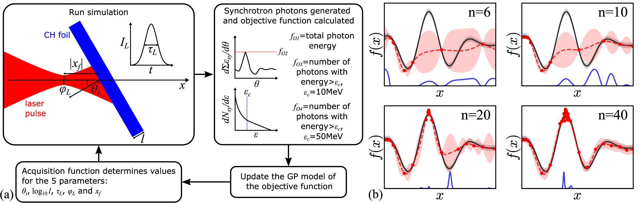
Figure 1.(a) The Bayesian optimization loop and schematic of the simulation setup. The synchrotron photon energy spectrum ( ) and angle-resolved yield (
 ) generated in each simulation are depicted to illustrate several of the objective functions. (b) An example of Bayesian optimization of a noisy 1D function showing the true function (black), the model (red) and the acquisition function (blue) for different numbers of iterations (
Previously, the same approach was applied for the optimization of laser-driven ion acceleration[67] using a single physical parameter in the objective function (maximum ion energy). Here this method is applied both for single and multiple physical parameters in the objective function, enabling the exploration of different objective functions to influence the trade-off in one required beam parameter against another.
3 2D parameter space scans of gamma ray emission
Before optimizing the interaction, the influence of a number of input parameters, including each of the chosen optimization parameters, was first explored in 2D parameter space scans. The target thickness was one of the varied parameters in each scan, enabling separation of the effect of RSIT, which can be controlled with target thickness[83], from the effect of varying each of the other parameters. Initially, in Figures 2(a)–2(c) a pulse with
![]()
Figure 2.(a) Percentage transmission of the laser pulse, (b) total electron energy in front of the plasma critical surface and in the laser skin depth averaged over the period of synchrotron emission and (c) laser-to-synchrotron photon energy conversion efficiency, all for varying target thickness and laser intensity. (d)–(f) Laser-to-synchrotron photon energy conversion efficiency for varying pulse duration, focal spot size and defocus, respectively, with target thickness.
To produce synchrotron radiation in these interactions, highly relativistic electrons are required in an intense electromagnetic field, and as changes to the target thickness cause a transition between transparent and opaque targets, the coupling of the laser energy to the electrons also changes[84]. Therefore, the total electron energy sampled along the
3.1 Laser-injected synchrotron emission
For increasing
3.2 Pulse duration, spot size and defocus
In Figures 2(d)–2(f), the synchrotron conversion efficiency is shown, where the laser energy is kept constant in the 2D simulation geometry corresponding to peak intensity
3.3 Stability
Although these results indicate that the most efficient synchrotron radiation source for a fixed laser pulse energy corresponds to the shortest pulse duration and smallest focal spot size focused onto the surface of a partially transmissive foil, the small Rayleigh length,
3.4 Scaling of the synchrotron conversion efficiency
The 2D parameter space scans provide target thickness-dependent scalings of
![]()
Figure 3.Scaling of the laser-to-synchrotron energy conversion efficiency with (a) peak laser intensity, (b) pulse duration and (c) focal spot FWHM, for varying target thickness. Power law fits are shown for the optimum target thicknesses (black) and for the thickest targets used (red;  for (a) and
  for (b) and (c)).
The use of ultrathin targets can increase
For constant laser pulse energy, the pulse duration is found to play a weaker role, with
3.5 Angle-of-incidence
The results for the final optimization parameter, the angle-of-incidence of the laser pulse on the target, are shown in Figure 4. In Figure 4(a), the synchrotron conversion efficiency is maximized for
![]()
Figure 4.(a) Laser-to-synchrotron photon energy conversion efficiency for varying angle-of-incidence and target thickness. (b) Electron spectra, sampled over the whole simulation space, averaged over the period of synchrotron emission for a 200 nm foil at normal and 45° incidence, and (c) the corresponding time-averaged  spectra.
3.6 Bremsstrahlung emission for varied laser intensity and target thickness
Until now, the discussion has focused on the generation of synchrotron radiation and how this depends on key laser and plasma parameters. Gamma radiation will, however, also be produced via bremsstrahlung emission in these interactions. Distinguishing between these two photon sources is important for the design of experiments that aim to investigate either mechanism.
In this investigation, thin foils of a low Z material have been selected to minimize the production of bremsstrahlung radiation. In Figure 5(a), the conversion efficiency to bremsstrahlung radiation,
![]()
Figure 5.(a) Laser-to-bremsstrahlung radiation energy conversion efficiency for varying laser intensity and target thickness. (b) Energy spectra for bremsstrahlung photons (solid) and synchrotron photons (dotted) for different target thicknesses. (c) The rate of energy conversion to bremsstrahlung radiation.
In Figure 5(b), the energy spectra of the bremsstrahlung and synchrotron radiation are shown for various target thicknesses, where
4 Application of Bayesian optimization
The scans discussed thus far vary only two input parameters at a time, over a
The parameter search space was defined as
| Parameter values at optimum | |||||
|---|---|---|---|---|---|
| Objective function | log | ||||
| 41.1 | –5 | 42.8 | 1 | 0.7 | |
| 26.4 | –5 | 30 | 1 | 0.57 | |
| 24.4 | –6.26 | 30 | 1 | 0.63 | |
| 70 | –7.3 | 30 | 1 | –4.33 | |
| 40.6 | –6.64 | 30 | 1 | 0.14 | |
| 18.3 | –5.23 | 30 | 1 | 0.85 | |
| 30.9 | –6.45 | 30 | 1 | 0.92 | |
Table 1. The objective functions maximized with Bayesian optimization and the parameters of the found optimum for each.
To optimize multiple properties of the photon emission, a series of different objective functions were considered. These include the ratio of the peak angle-resolved energy of synchrotron emission to the total bremsstrahlung radiation energy (
4.1 Optimization of individual synchrotron emission properties
The resulting synchrotron and bremsstrahlung photon energy spectra and the angle-resolved energy of synchrotron radiation are shown in Figures 6(a)–6(c), respectively, for the optimum of each objective function. In maximizing the total energy of synchrotron radiation with
![]()
Figure 6.Synchrotron and bremsstrahlung radiation for the objective function optima in Table 1, for which  fs
fs m
m W cm−2. (a) Synchrotron photon energy spectra, (b) bremsstrahlung photon energy spectra and (c) angular profiles of total emitted synchrotron photon energy.
4.2 Mitigation of the bremsstrahlung emission
In maximizing the ratio of the directional energy of synchrotron emission to the bremsstrahlung emission for
The objective functions
4.3 Intensity
For all of these optimization results, the best spot size corresponds to the minimum,
5 Optimization in the synchrotron dominated regime
The optimization results discussed thus far are for conditions in which the synchrotron emission is relatively weak. The laser energy was increased by a factor of 10, corresponding to
| Parameter values at optimum | |||||
|---|---|---|---|---|---|
| Objective function | log | ||||
| 38 | –5.6 | 30 | 1 | 1.76 | |
| 45.6 | –5 | 100 | 1 | 1.93 | |
| 0 | –5.22 | 30 | 1 | 1.89 | |
| 70 | –7.3 | 30 | 5.33 | –50 | |
| 54.3 | –5.91 | 30 | 1 | 0.19 | |
Table 2. The objective functions used for optimization with laser intensity of  fs
fs m
m W cm−2, and the parameters of the found optima.
5.1 Angle-resolved synchrotron emission
The optimum of
![]()
Figure 7.Synchrotron and bremsstrahlung radiation for the objective function optima in Table 2, for which  fs
fs m
m W cm−2. (a) Synchrotron photon energy spectra, (b) bremsstrahlung photon energy spectra and (c) angular profiles of total emitted synchrotron photon energy.
Optimization of total synchrotron emission with
5.2 Mitigation of the bremsstrahlung emission
The optimum parameters to reduce bremsstrahlung radiation whilst maximizing angle-resolved synchrotron emission for
The angle-resolved synchrotron emission for the optimum of
The optimization results found here indicate the need to maximize the laser intensity interacting with the surface of solid targets to produce the strongest sources of synchrotron radiation. Rotation of the target in the plane of polarization of the laser pulse can produce the highest peak angle-resolved synchrotron emission, and the use of ultrathin foils is a very effective method of reducing the bremsstrahlung emission to generate a purer source of synchrotron emission. The optimization of multiple objectives in a single objective function can be effectively controlled with careful definition of the objective function, and use of such methods is demonstrated to generate comparable to best-case synchrotron emission in sub-μm foils where the bremsstrahlung emission is still strongly mitigated.
6 Angle-of-incidence dependence of the forward synchrotron emission
Through applying Bayesian optimization, the angle-of-incidence has been identified as a critical parameter influencing the spatial profile of the synchrotron emission. This was investigated in more detail using laser parameters
In Figure 8(a), the maximum value of
![]()
Figure 8.(a) Maximum value of  as a function of the angle-of-incidence for synchrotron photons emitted in angular ranges
  (black) and
  (blue), where
  m,
m,  W cm−2,
  m,
m,  fs and
  . The optima in
  in the ranges
  (dashed) and
  (solid) averaged over the period of synchrotron emission. (c) Energy-weighted mean angle between the electron trajectory and the propagation direction of the local electromagnetic field (left-hand axis) and mean electron quantum parameter (right-hand axis) for each group of electrons in (b). (d)–(f) The electron density for
  , 22.5° and 60°, respectively, where the total momentum of fast electrons (arrows) and the
  W cm−2 contour (red) are also shown.
The synchrotron radiation is caused by highly relativistic electrons within the laser field, and the direction of the emitted radiation is predominantly in the electron direction of motion,
The equation for
Example snapshots of the electron density on the simulation grid are shown in Figures 8(d)–8(f) close to the time of peak synchrotron emission for
When the target is rotated to
The Bayesian optimization results in Table 2 and Figure 7(c) indicate a laser intensity dependence of the optimum angle-of-incidence for producing the highest peak angle-resolved synchrotron emission, with the best results for
7 Spatial control of synchrotron emission in 3D simulations
The investigation of the angle-of-incidence, which is highly influential on the spatial profile of synchrotron emission, identified through the optimization scans and explored in 2D in the previous section, was extended with 3D simulations. The synchrotron emission is dominated by electrons accelerated and injected from the edges further into the laser spatial profile due to interaction with the laser electric field, and therefore the spatial profile of synchrotron emission should change as the polarization of the laser light changes. This motivates simulations in which we separately test the effect of p-, s-, left-hand c- and right-hand c- polarized laser light on the spatial profile of synchrotron emission for varying angle-of-incidence.
A lower plasma density of
The spatial profiles of synchrotron emission are shown as a function of
Figure 9(a) shows the maximum angle-resolved energy of synchrotron emission of the two azimuthally defined regions corresponding to
For an s- (along
![]()
Figure 9.3D simulation results for synchrotron photon emission for different laser light polarization states. Peak angle-resolved synchrotron energy emitted in each direction for (a) p-polarization, (b) s-polarization and (c) left-hand and right-hand circular polarization. (d)–(f) Conversion efficiency to synchrotron radiation for p-, s- and both left-hand and right-hand circular polarization, respectively.
Finally, in Figures 9(c) and 9(f), results for both left-hand circular polarization (LHCP) and right-hand circular polarization (RHCP) are shown. For c-polarization, two lobes are not produced for normal incidence, but an annular structure instead[27], due to the rotating electric field pulling electrons into the focal spot from all around the sides of the hole bored plasma cavity by the time it has completed one cycle. The magnitude of the angle-resolved energy of synchrotron emission in the full angular range is shown in Figure 9(c). For normal incidence it is approximately 0.5 J sr−1, which is approximately 1 J sr−1 lower than for linear polarization. However, this more than doubles in rotating the target to
The results in Figure 9 indicate that p-polarization and
![]()
Figure 10.Angular profiles of the total energy of synchrotron emission in the forward direction ( ) in 3D simulations for different laser light polarization states and angles-of-incidence.
For p-polarization a double lobe structure is shown for
For
For LHCP and RHCP in Figure 10, synchrotron radiation is generated with an annular spatial profile for normal incidence. Rotation of the target, however, produces an asymmetry in the angular distribution of radiation. One section of the annular structure becomes thicker and brighter, the hole of the annulus moves away from
For
A limited number of 3D simulations were performed for
The strongest angle-resolved synchrotron emission of 160 J sr−1 was generated for p-polarization,
8 Summary
In summary, Bayesian optimization has been applied to the generation of synchrotron radiation in ultrahigh-intensity laser interactions with CH foils in 2D simulations. Optimization of individual properties is shown, and control of simultaneous optimization of the conflicting objectives of maximizing synchrotron production and minimizing bremsstrahlung emission is demonstrated with changes to the objective function, including the use of an acceptance function.
Through the use of machine learning-based optimization, the angle-of-incidence is identified as a critical parameter in achieving the greatest angle-resolved synchrotron emission. Further 2D and 3D simulations of a
The changes induced in the synchrotron spatial profile with laser polarization and angle-of-incidence may enable such radiation to be more easily distinguishable from bremsstrahlung emission, and enhance studies of the QED-plasma physics in these interactions. The demonstrated control of the synchrotron emission is also useful for the application of this intense source of high-energy photons. The work presented here may be further extended by considering the generation of electron–positron pairs from the high-energy photons in the intense laser fields, and the influence of parameters not explored, such as the front surface density scale length, the spatial-intensity contrast[89] and different target structures.
References
[1] H. Schwoerer, P. Gibbon, S. Düsterer, R. Behrens, C. Ziener, C. Reich, R. Sauerbrey. Phys. Rev. Lett., 86, 2317(2001).
[2] C. D. Chen, A. J. Kemp, F. Pérez, A. Link, F. N. Beg, S. Chawla, M. H. Key, H. McLean, A. Morace, Y. Ping, A. Sorokovikova, R. B. Stephens, M. Streeter, B. Westover, P. K. Patel. Phys. Plasmas, 20, 052703(2013).
[3] S. Singh, C. D. Armstrong, N. Kang, L. Ren, H. Liu, N. Hua, D. R. Rusby, O. Klimo, R. Versaci, Y. Zhang, M. Sun, B. Zhu, A. Lei, X. Ouyang, L. Lancia, A. L. Garcia, A. Wagner, T. Cowan, J. Zhu, T. Schlegel, S. Weber, P. McKenna, D. Neely, V. Tikhonchuk, D. Kumar. Plasma Phys. Control. Fusion, 63, 035004(2021).
[4] A. Rousse, P. Audebert, J. P. Geindre, F. Falliès, J. C. Gauthier, A. Mysyrowicz, G. Grillon, A. Antonetti. Phys. Rev. E, 50, 2200(1994).
[5] R. D. Edwards, M. A. Sinclair, T. J. Goldsack, K. Krushelnick, F. N. Beg, E. L. Clark, A. E. Dangor, Z. Najmudin, M. Tatarakis, B. Walton, M. Zepf, K. W. D. Ledingham, I. Spencer, P. A. Norreys, R. J. Clarke, R. Kodama, Y. Toyama, M. Tampo. Appl. Phys. Lett., 80, 2129(2002).
[6] J. Galy, M. Maučec, D. J. Hamilton, R. Edwards, J. Magill. New J. Phys., 9, 23(2007).
[7] C. Courtois, R. Edwards, A. C. La Fontaine, C. Aedy, M. Barbotin, S. Bazzoli, L. Biddle, D. Brebion, J. L. Bourgade, D. Drew, M. Fox, M. Gardner, J. Gazave, J. M. Lagrange, O. Landoas, L. Le Dain, E. Lefebvre, D. Mastrosimone, N. Pichoff, G. Pien, M. Ramsay, A. Simons, N. Sircombe, C. Stoeckl, K. Thorp. Phys. Plasmas, 18, 023101(2011).
[8] C. M. Brenner, S. R. Mirfayzi, D. R. Rusby, C. Armstrong, A. Alejo, L. A. Wilson, R. Clarke, H. Ahmed, N. M. H. Butler, D. Haddock, A. Higginson, A. McClymont, C. Murphy, M. Notley, P. Oliver, R. Allott, C. Hernandez-Gomez, S. Kar, P. McKenna, D. Neely. Plasma Phys. Control. Fusion, 58, 014039(2016).
[9] K. W. D. Ledingham, I. Spencer, T. McCanny, R. P. Singhal, M. I. K. Santala, E. Clark, I. Watts, F. N. Beg, M. Zepf, K. Krushelnick, M. Tatarakis, A. E. Dangor, P. A. Norreys, R. Allott, D. Neely, R. J. Clark, A. C. Machacek, J. S. Wark, A. J. Cresswell, D. C. W. Sanderson, J. Magill. Phys. Rev. Lett., 84, 899(2000).
[10] E. P. Liang, S. C. Wilks, M. Tabak. Phys. Rev. Lett., 81, 4887(1998).
[11] T. E. Cowan, M. D. Perry, M. H. Key, T. R. Ditmire, S. P. Hatchett, E. A. Henry, J. D. Moody, M. J. Moran, D. M. Pennington, T. W. Phillips, T. C. Sangster, J. A. Sefcik, M. S. Singh, R. A. Snavely, M. A. Stoyer, S. C. Wilks, P. E. Young, Y. Takahashi, B. Dong, W. Fountain, T. Parnell, J. Johnson, A. W. Hunt, T. Kühl. Laser Part. Beams, 17, 773(1999).
[12] B. Shen, J. Meyer-ter Vehn. Phys. Rev. E, 65, 016405(2001).
[13] H. Chen, S. C. Wilks, D. D. Meyerhofer, J. Bonlie, C. D. Chen, S. N. Chen, C. Courtois, L. Elberson, G. Gregori, W. Kruer, O. Landoas, J. Mithen, J. Myatt, C. D. Murphy, P. Nilson, D. Price, M. Schneider, R. Shepherd, C. Stoeckl, M. Tabak, R. Tommasini, P. Beiersdorfer. Phys. Rev. Lett., 105, 015003(2010).
[14] B. Martinez, M. Lobet, R. Duclous, E. d’Humières, L. Gremillet. Phys. Plasmas, 26, 103109(2019).
[15] J. W. Yoon, Y. G. Kim, I. W. Choi, J. H. Sung, H. W. Lee, S. K. Lee, C. H. Nam. Optica, 8, 630(2021).
[16] F. Sauter. Z. Phys., 69, 742(1931).
[17] J. Schwinger. Phys. Rev., 82, 664(1951).
[18] A. M. Fedotov, N. B. Narozhny, G. Mourou, G. Korn. Phys. Rev. Lett., 105, 080402(2010).
[19] G. Breit, J. A. Wheeler. Phys. Rev., 46, 1087(1934).
[20] A. R. Bell, J. G. Kirk. Phys. Rev. Lett., 101, 200403(2008).
[21] C. P. Ridgers, C. S. Brady, R. Duclous, J. G. Kirk, K. Bennett, T. D. Arber, A. P. L. Robinson, A. R. Bell. Phys. Rev. Lett., 108, 165006(2012).
[22] J. M. Cole, K. T. Behm, E. Gerstmayr, T. G. Blackburn, J. C. Wood, C. D. Baird, M. J. Duff, C. Harvey, A. Ilderton, A. S. Joglekar, K. Krushelnick, S. Kuschel, M. Marklund, P. McKenna, C. D. Murphy, K. Poder, C. P. Ridgers, G. M. Samarin, G. Sarri, D. R. Symes, A. G. R. Thomas, J. Warwick, M. Zepf, Z. Najmudin, S. P. D. Mangles. Phys. Rev. X, 8, 011020(2018).
[23] K. Poder, M. Tamburini, G. Sarri, A. Di Piazza, S. Kuschel, C. D. Baird, K. Behm, S. Bohlen, J. M. Cole, D. J. Corvan, M. Duff, E. Gerstmayr, C. H. Keitel, K. Krushelnick, S. P. D. Mangles, P. McKenna, C. D. Murphy, Z. Najmudin, C. P. Ridgers, G. M. Samarin, D. R. Symes, A. G. R. Thomas, J. Warwick, M. Zepf. Phys. Rev. X, 8, 031004(2018).
[24] C. S. Brady, C. P. Ridgers, T. D. Arber, A. R. Bell, J. G. Kirk. Phys. Rev. Lett., 109, 245006(2012).
[25] T. Nakamura, J. K. Koga, T. Zh. Esirkepov, M. Kando, G. Korn, S. V. Bulanov. Phys. Rev. Lett., 108, 195001(2012).
[26] C. S. Brady, C. P. Ridgers, T. D. Arber, A. R. Bell. Phys. Plasmas, 21, 033108(2014).
[27] L. L. Ji, A. Pukhov, E. N. Nerush, I. Yu. Kostyukov, B. F. Shen, K. U. Akli. Phys. Plasmas, 21, 023109(2014).
[28] P. Hadjisolomou, T. M. Jeong, S. V. Bulanov. Sci. Rep., 12, 17143(2022).
[29] P. Hadjisolomou, T. M. Jeong, P. Valenta, D. Kolenaty, R. Versaci, V. Olšovcová, C. P. Ridgers, S. V. Bulanov. J. Plasma Phys., 88, 905880104(2022).
[30] P. Zhang, C. P. Ridgers, A. G. R. Thomas. New J. Phys., 17, 043051(2015).
[31] D. A. Serebryakov, E. N. Nerush. Quantum Electron., 46, 299(2016).
[32] D. J. Stark, T. Toncian, A. V. Arefiev. Phys. Rev. Lett., 116, 185003(2016).
[33] H. X. Chang, B. Qiao, T. W. Huang, Z. Xu, C. T. Zhou, Y. Q. Gu, X. Q. Yan, M. Zepf, X. T. He. Sci. Rep., 7, 45031(2017).
[34] H.-Z. Li, T.-P. Yu, J.-J. Liu, Y. Yin, X.-L. Zhu, R. Capdessus, F. Pegoraro, Z.-M. Sheng, P. McKenna, F.-Q. Shao. Sci. Rep., 7, 17312(2017).
[35] R. Capdessus, M. King, D. Del Sorbo, M. Duff, C. P. Ridgers, P. McKenna. Sci. Rep., 8, 9155(2018).
[36] Z. Gong, R. H. Hu, H. Y. Lu, J. Q. Yu, D. H. Wang, E. G. Fu, C. E. Chen, X. T. He, X. Q. Yan. Plasma Phys. Control. Fusion, 60, 044004(2018).
[37] Y.-J. Gu, O. Klimo, S. V. Bulanov, S. Weber. Commun. Phys., 1, 93(2018).
[38] O. Jansen, T. Wang, D. J. Stark, E. d’Humières, T. Toncian, A. V. Arefiev. Plasma Phys. Control. Fusion, 60, 054006(2018).
[39] K. V. Lezhnin, P. V. Sasorov, G. Korn, S. V. Bulanov. Phys. Plasmas, 25, 123105(2018).
[40] W. Luo, S.-D. Wu, W.-Y. Liu, Y.-Y. Ma, F.-Y. Li, T. Yuan, J.-Y. Yu, M. Chen, Z.-M. Sheng. Plasma Phys. Control. Fusion, 60, 095006(2018).
[41] B. Martinez, E. d’Humières, L. Gremillet. Plasma Phys. Control. Fusion, 60, 074009(2018).
[42] W.-M. Wang, Z.-M. Sheng, P. Gibbon, L.-M. Chen, Y.-T. Li, J. Zhang. Proc. Natl. Acad. Sci. U.S.A, 115, 9911(2018).
[43] X.-L. Zhu, T.-P. Yu, M. Chen, S.-M. Weng, Z.-M. Sheng. New J. Phys., 20, 083013(2018).
[44] T. W. Huang, C. M. Kim, C. T. Zhou, M. H. Cho, K. Nakajima, C. M. Ryu, S. C. Ruan, C. H. Nam. New J. Phys., 21, 013008(2019).
[45] D. A. Serebryakov, T. M. Volkova, E. N. Nerush, I. Y. Kostyukov. Plasma Phys. Control. Fusion, 61, 074007(2019).
[46] Y. Zhao, J. Liu, Y. Li, G. Xia. Plasma Phys. Control. Fusion, 61, 065010(2019).
[47] T. Wang, X. Ribeyre, Z. Gong, O. Jansen, E. d’Humières, D. Stutman, T. Toncian, A. Arefiev. Phys. Rev. Appl., 13, 054024(2020).
[48] X.-B. Wang, G.-Y. Hu, Z.-M. Zhang, Y.-Q. Gu, B. Zhao, Y. Zuo, J. Zheng. High Power Laser Sci. Eng., 8, e34(2020).
[49] K. Xue, Z.-K. Dou, F. Wan, T.-P. Yu, W.-M. Wang, J.-R. Ren, Q. Zhao, Y.-T. Zhao, Z.-F. Xu, J.-X. Li. Matter Radiat. Extrem., 5, 054402(2020).
[50] Y. Zhao, J. Liu, G. Xia, A. Bonatto. Phys. Plasmas, 27, 073106(2020).
[51] L. Fedeli, A. Sainte-Marie, N. Zaim, M. Thévenet, J. L. Vay, A. Myers, F. Quéré, H. Vincenti. Phys. Rev. Lett., 127, 114801(2021).
[52] P. Hadjisolomou, T. M. Jeong, P. Valenta, G. Korn, S. V. Bulanov. Phys. Rev. E, 104, 015203(2021).
[53] Y. He, T. G. Blackburn, T. Toncian, A. V. Arefiev. Commun. Phys., 4, 139(2021).
[54] S. Chintalwad, S. Krishnamurthy, B. Ramakrishna, C. P. Ridgers. Phys. Rev. E, 105, 025205(2022).
[55] F. Wan, C. Lv, M. Jia, H. Sang, B. Xie. Eur. Phys. J. D, 71, 236(2017).
[56] J. Vyskočil, O. Klimo, S. Weber. Plasma Phys. Control. Fusion, 60, 054013(2018).
[57] J. Vyskočil, E. Gelfer, O. Klimo. Plasma Phys. Control. Fusion, 62, 064002(2020).
[58] S. Morris, A. Robinson, C. Ridgers. Phys. Plasmas, 28, 103304(2021).
[59] B. Martinez, E. d’Humières, L. Gremillet. Phys. Rev. Res., 2, 043341(2020).
[60] V. A. Vshivkov, N. M. Naumova, F. Pegoraro, S. V. Bulanov. Phys. Plasmas, 5, 2727(1998).
[61] S. Palaniyappan, B. M. Hegelich, H.-C. Wu, D. Jung, D. C. Gautier, L. Yin, B. J. Albright, R. P. Johnson, T. Shimada, S. Letzring, D. T. Offermann, J. Ren, C. Huang, R. Hörlein, B. Dromey, J. C. Fernandez, R. C. Shah. Nat. Phys., 8, 763(2012).
[62] C. S. Brady, C. P. Ridgers, T. D. Arber, A. R. Bell. Plasma Phys. Control. Fusion, 55, 124016(2013).
[63] B. Shahriari, K. Swersky, Z. Wang, R. P. Adams, N. de Freitas. Proc. IEEE, 104, 148(2016).
[64] P. I. Frazier. Recent Advances in Optimization and Modeling of Contemporary Problems, 255(2018).
[65] S. Jalas, M. Kirchen, P. Messner, P. Winkler, L. Hübner, J. Dirkwinkel, M. Schnepp, R. Lehe, A. R. Maier. Phys. Rev. Lett., 126, 104801(2021).
[66] R. J. Shalloo, S. J. D. Dann, J.-N. Gruse, C. I. D. Underwood, A. F. Antoine, C. Arran, M. Backhouse, C. D. Baird, M. D. Balcazar, N. Bourgeois, J. A. Cardarelli, P. Hatfield, J. Kang, K. Krushelnick, S. P. D. Mangles, C. D. Murphy, N. Lu, J. Osterhoff, K. Põder, P. P. Rajeev, C. P. Ridgers, S. Rozario, M. P. Selwood, A. J. Shahani, D. R. Symes, A. G. R. Thomas, C. Thornton, Z. Najmudin, M. J. V. Streeter. Nat. Commun., 11, 6355(2020).
[67] E. J. Dolier, M. King, R. Wilson, R. J. Gray, P. McKenna. New J. Phys., 24, 073025(2022).
[68] A. Gonoskov, E. Wallin, A. Polovinkin, I. Meyerov. Sci. Rep., 9, 7043(2019).
[69] B. Z. Djordjević, A. J. Kemp, J. Kim, R. A. Simpson, S. C. Wilks, T. Ma, D. A. Mariscal. Phys. Plasmas, 28, 043105(2021).
[70] Z.-H. He, B. Hou, V. Lebailly, J. A. Nees, K. Krushelnick, A. G. R. Thomas. Nat. Commun., 6, 7156(2015).
[71] Z.-H. He, B. Hou, G. Gao, V. Lebailly, J. A. Nees, R. Clarke, K. Krushelnick, A. G. R. Thomas. Phys. Plasmas, 22, 056704(2015).
[72] S. J. D. Dann, C. D. Baird, N. Bourgeois, O. Chekhlov, S. Eardley, C. D. Gregory, J.-N. Gruse, J. Hah, D. Hazra, S. J. Hawkes, C. J. Hooker, K. Krushelnick, S. P. D. Mangles, V. A. Marshall, C. D. Murphy, Z. Najmudin, J. A. Nees, J. Osterhoff, B. Parry, P. Pourmoussavi, S. V. Rahul, P. P. Rajeev, S. Rozario, J. D. E. Scott, R. A. Smith, E. Springate, Y. Tang, S. Tata, A. G. R. Thomas, C. Thornton, D. R. Symes, M. J. V. Streeter. Phys. Rev. Accel. Beams, 22, 041303(2019).
[73] J. R. Smith, C. Orban, J. T. Morrison, K. M. George, G. K. Ngirmang, E. A. Chowdhury, W. M. Roquemore. New J. Phys., 22, 103067(2020).
[74] K. Deb. Search Methodologies: Introductory Tutorials in Optimization and Decision Support Techniques, 403(2014).
[75] M. T. M. Emmerich, A. H. Deutz. Nat. Comput., 17, 585(2018).
[76] R. Roussel, A. Hanuka, A. Edelen. Phys. Rev. Accel. Beams, 24, 062801(2021).
[77] F. Irshad, S. Karsch, A. Döpp. Phys. Rev. Res., 5, 013063(2023).
[78] T. D. Arber, K. Bennett, C. S. Brady, A. Lawrence-Douglas, M. G. Ramsay, N. J. Sircombe, P. Gillies, R. G. Evans, H. Schmitz, A. R. Bell, C. P. Ridgers. Plasma Phys. Control. Fusion, 57, 113001(2015).
[79] C. P. Ridgers, J. G. Kirk, R. Duclous, T. G. Blackburn, C. S. Brady, K. Bennett, T. D. Arber, A. R. Bell. J. Comput. Phys., 260, 273(2014).
[80] D. Wu, X. T. He, W. Yu, S. Fritzsche. High Power Laser Sci. Eng., 6, e50(2018).
[81] F. Pedregosa, G. Varoquaux, A. Gramfort, V. Michel, B. Thirion, O. Grisel, M. Blondel, P. Prettenhofer, R. Weiss, V. Dubourg, J. Vanderplas, A. Passos, D. Cournapeau, M. Brucher, M. Perrot, É. Duchesnay, J. Mach. Learn. Res., 12, 2825(2011).
[82] M. Hoffman, E. Brochu, N. de FreitasUAI’11: Proceedings of the Twenty-Seventh Conference on Uncertainty in Artificial Intelligence. , , and , in (AUAI Press, ), p. ., 327(2011).
[83] J. Goodman, M. King, R. Wilson, R. J. Gray, P. McKenna. New J. Phys., 24, 053016(2022).
[84] S. D. R. Williamson, R. J. Gray, M. King, R. Wilson, R. J. Dance, C. Armstrong, D. R. Rusby, C. Brabetz, F. Wagner, B. Zielbauer, V. Bagnoud, D. Neely, P. McKenna. New J. Phys., 22, 053044(2020).
[85] S. C. Wilks, W. L. Kruer, M. Tabak, A. B. Langdon. Phys. Rev. Lett., 69, 1383(1992).
[86] A. P. L. Robinson, P. Gibbon, M. Zepf, S. Kar, R. G. Evans, C. Bellei. Plasma Phys. Control. Fusion, 51, 024004(2009).
[87] P. M. Nilson, J. R. Davies, W. Theobald, P. A. Jaanimagi, C. Mileham, R. K. Jungquist, C. Stoeckl, I. A. Begishev, A. A. Solodov, J. F. Myatt, J. D. Zuegel, T. C. Sangster, R. Betti, D. D. Meyerhofer. Phys. Rev. Lett., 108, 085002(2012).
[88] E. N. Nerush, I. Yu. Kostyukov, L. Ji, A. Pukhov. Phys. Plasmas, 21, 013109(2014).
[89] R. Wilson, M. King, N. M. H. Butler, D. C. Carroll, T. P. Frazer, M. J. Duff, A. Higginson, R. J. Dance, J. Jarrett, Z. E. Davidson, C. D. Armstrong, H. Liu, S. J. Hawkes, R. J. Clarke, D. Neely, R. J. Gray, P. McKenna. Sci. Rep., 12, 1910(2022).


Set citation alerts for the article
Please enter your email address

© Copyright 2018-2021 | Chinese Laser Press. All Rights Reserved 沪ICP备15018463号-20