
Xiaodong Yu, Muhui Jiang, Gongda Zhang, Chuanyang Wang. Influences of Copper Film Width on Polycarbonate Welding Strength and Weld Morphological Characteristics[J]. Acta Optica Sinica, 2021, 41(14): 1414001
- Acta Optica Sinica
- Vol. 41, Issue 14, 1414001 (2021)
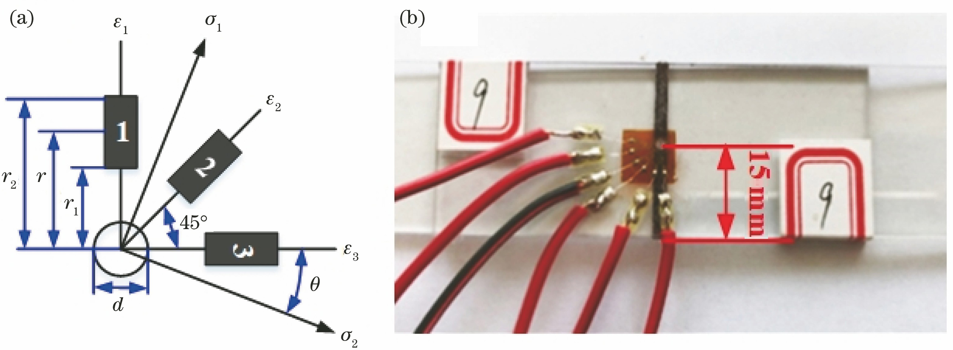
Fig. 1. Schematic of laser transmission welding
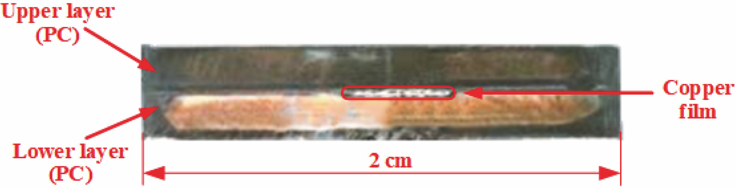
Fig. 2. Strain gage pasting. (a) Schematic; (b) physical image
Fig. 3. Structural diagram of cross-section of weld part after polishing
Fig. 4. Cross-sectional morphologies of weldments for different laser absorption layers. (a) CB; (b) CWCB
Fig. 5. Deformation features of weldments for different CWCB widths when P=45 W and v=6 mm/s. (a) w=1.0 mm; (b) w=1.5 mm; (c) w=2.0 mm; (d) w=2.5 mm; (e) w=3.0 mm; (f) w=3.5 mm
Fig. 6. Effects of CWCB width on deformation depth and area
Fig. 7. Overflow morphologies on weld edges for different CWCB widths. (a) w=1 mm; (b) w=2 mm; (c) w=3 mm
Fig. 8. EDS analysis images of cross section. (a) Elemental distribution; (b) elemental distribution for C; (c) elemental distribution for O; (d) elemental distribution for Cu
Fig. 9. Schematic of compositions of weld seam
Fig. 10. Effects of CWCB width on different variables. (a) Welding strength and weld width; (b) residual stress
|
Table 1. Thermodynamic parameters of PC
|
Table 2. Technical parameters of laser welding machine WFD120
|
Table 3. Weldability comparison among PC plates with different absorption layers

Set citation alerts for the article
Please enter your email address
© Copyright 2018-2021 | Chinese Laser Press. All Rights Reserved 沪ICP备15018463号-20