
Di Wang, Kang Ying, Wenping Li, Wu Zhang, Jingwen Gong, Dong Liang, Wei Jiang, Qinggui Tan, Xiaojun Li. Design and Inscription of Optical Filters Based on Multi-Phase-Shifted Fiber Bragg Gratings[J]. Acta Optica Sinica, 2020, 40(22): 2206002
- Acta Optica Sinica
- Vol. 40, Issue 22, 2206002 (2020)
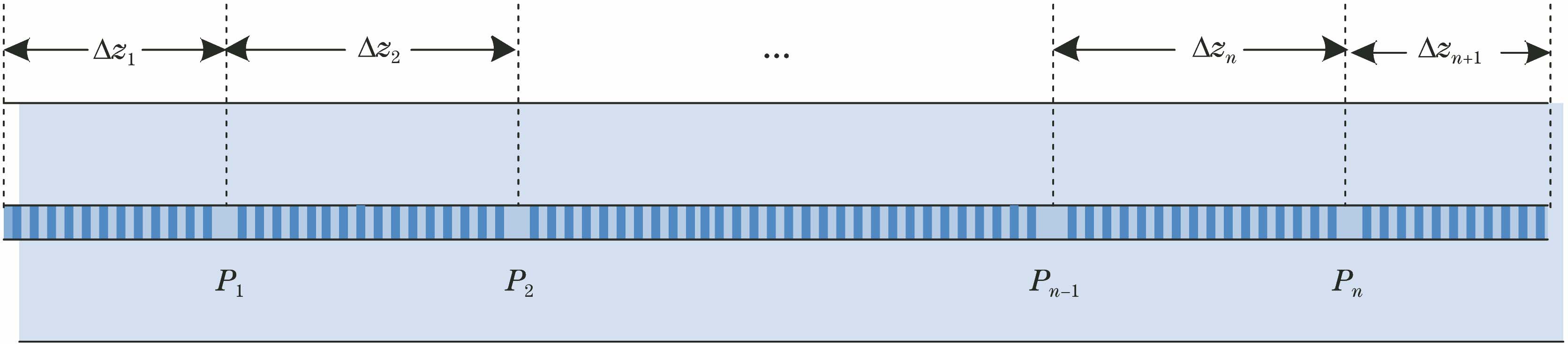
Fig. 1. Schematic diagram of an MPSFBG
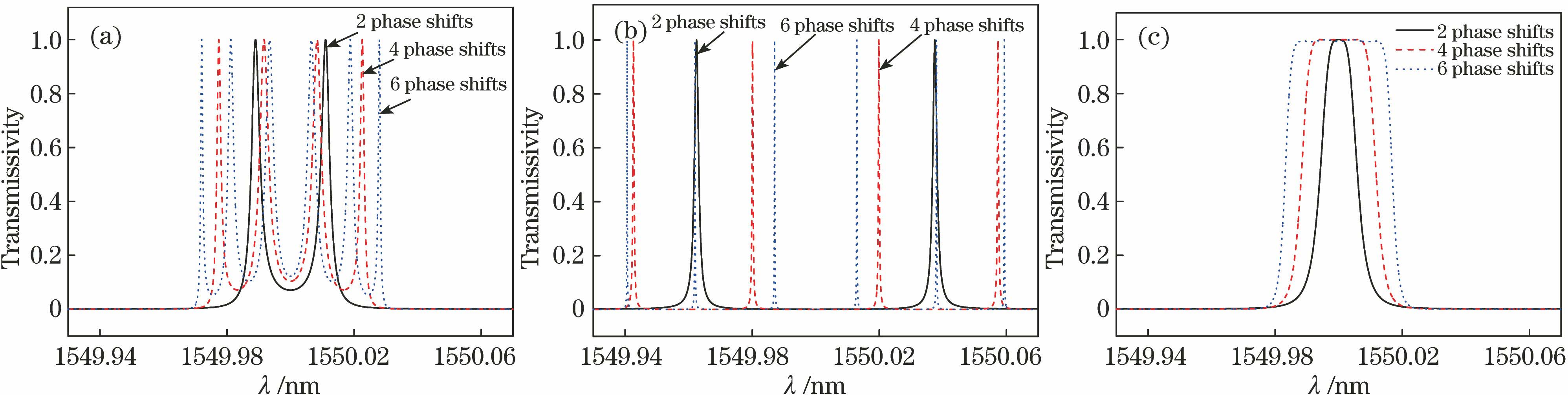
Fig. 2. Spectra of MPSFBGs with 2, 4, and 6 phase shifts. The ratios of the lengths of subgratings are (a) 1∶1∶1, 1∶1 ∶1 ∶1 ∶1, and 1∶1∶1∶1∶1∶1∶1; (b)3∶1∶3, 3∶1∶1∶1∶3, and 3∶1∶1∶1∶1∶1∶3; (c) 1∶2∶1, 1∶2.3∶2.6∶2.3∶1, and 1∶2.2∶2.6∶2.7∶2.6∶2.2∶1, respectively
Fig. 3. Simulated transmission spectra and parametric curves of MPSFBGs with different number of phase shifts when the 3 dB bandwidth of filters is 500 MHz. (a) Spectra of MPSFBGs; (b) shape factor of filter and the tolerance of phase shifts location versus the number of phase shifts of MPSFBG
Fig. 4. Bandwidth and shape factor of filter versus coupling coefficient κ of MPSFBG when the length of MPSFBG is 30 mm. (a) Bandwidth; (b) shape factor
Fig. 5. Bandwidth of filter and shape factor of filter versus coupling length l of MPSFBG
Fig. 6. Influence of process errors on the spectrum of double-phase-shifted FBG. (a) Length ratio of fiber grating; (b) phase shifts δφ
Fig. 7. Experimental principle. (a) Schematic of inscription system with the phase mask; (b) schematic diagram of MPSFBGs inscription
Fig. 8. Tolerance of phase shifts position versus the bandwidth of transmission peak
Fig. 9. Spectra of double-phase-shifted FBG prepared. (a) Without phase shift error; (b) with phase shift error
Fig. 10. Tolerance of differences between phase shifts versus bandwidth of transmission peak
Fig. 11. Spectrum of double-phase-shifted FBG with the coupling coefficient of 225 m-1 and the length of 30 mm
Fig. 12. Spectra of triple-phase-shifted FBG with different parameters. (a) Coupling coefficient of 225 m-1, the length of 30 mm, loss coefficient of 0.72 m-1; (b) coupling coefficient of 330 m-1, the length of 30 mm, loss coefficient of 1 m-1
Fig. 13. Change in the tolerance of position of phase shifts and the tolerance of differences between phase shifts versus the length of the fiber gratings. (a) Tolerance of phase shifts position; (b) tolerance of differences
Fig. 14. Loss of transmission peak versus length of the fiber gratings considering UV-induced loss
|
Table 1. Ratios of the lengths of each subgratings in the MPSFBGs

Set citation alerts for the article
Please enter your email address
© Copyright 2018-2021 | Chinese Laser Press. All Rights Reserved 沪ICP备15018463号-20