Abstract
In our Letter, we selected several commercial optical transceivers, which consist of single-channel transceiver modules, parallel transmitting and receiving modules, and Ethernet passive optical network (EPON) optical line terminal (OLT) and optical network unit (ONU) modules, to do the total ionizing dose (TID) testing via the gamma-ray radiation method. The changing of current and receiver sensitivity of optical transceivers is discussed and analyzed. Based on the TID testing exposed to a TID of 50 krad (Si) at a dose rate of about 0.1 rad (Si)/s, the performance of single-channel transceivers and parallel receiving modules has not changed after 50 krad (Si) exposure, the parallel transmitting and EPON ONU modules have not worked after 40 krad (Si) and 47 krad (Si) exposure, the EPON OLT module has bit error in the process of irradiation, and it can work well after annealing; the reason for the error of OLT is analyzed. Finally, based on the theoretical analysis and testing results, this Letter provides several design suggestions to improve the reliability for optical transceivers, which can be referenced by satellite system designation for various space missions.Recently, demand for new higher bandwidth services, higher transmission data rate, and superior reliability is beginning to drive the deployment of optical communication technology in space information networks[1–3]. The high-performance, high-data-rate, and low-cost optical transceivers are being considered as a key device in spaceflight projects[4–8]. However, owing to the effect of galactic cosmic rays, solar flares, and trapped particles in the earth radiation belts, the optical transceiver is easily affected by the effect of space radiation, for example, single-event effects (SEE), total ionizing dose (TID), and displacement damage (DDD)[9–12], especially for TID. The TID hazard originates from the space environment and includes contributions from charged particles (electrons, ions, and secondary charged particles), neutrons that undergo nuclear collisions to produce charged secondaries, and primary photons from the environment and electron bremsstrahlung[13]. However, many researches have been focused on the effects and analysis of the TID on complementary metal–oxide–semiconductor (CMOS), metal–oxide–semiconductor (MOS) devices, optoelectronic devices, and materials[12–17]. There is little research on the radiation characteristics of optical transceivers.
The space radiation environment is the main factor that causes the degradation and failure of optical transceivers. The radiation environment mainly includes particle radiation, photon radiation and the particles that cause the total ionization damage. Ionization damage refers to the excitation of high-energy charged particles or rays that interact with atoms after they are incident on the semiconductor material. For semiconductor materials, this excitation causes electrons to transit from the valence band to the conduction band, creating electron–hole pairs. Electrons and holes can recombine or displace under the action of the electric field or temperature. Relative to electrons, the mobility of holes is small and easily captured. The trapping of holes increases the leakage current and power consumption and degrades the performance of the device[18,19]. Usually, ionizing radiation takes a few forms: alpha, beta, and neutron particles and gamma () and X rays. As quanta have high energy (about 1 MeV), this results in high penetrating power and weak dependence of the TID in active areas of the device under test (DUT)[20,21]. Therefore, the ray and X ray are generally used to simulate the ionization effect on the ground. Cobalt-60 is almost solely used as the radiation source for industrial use now, mainly because of its easy production method and its non-solubility in water[22–24].
In this Letter, we selected several commercial optical transceivers consisting of a single-channel transceiver, parallel transmitter and receiver, and Ethernet passive optical network (EPON) optical line terminal (OLT) and optical network unit (ONU) modules, which are produced by Hisense Corporation, to do the TID testing via -ray radiation, which is exposed to a total ionizing dose of 50 krad (Si) at a dose rate of about 0.1 rad (Si)/s. Further, the performance of single-channel transceivers and parallel receiving modules has not changed after 50 krad (Si) exposure, the parallel transmitting and EPON ONU modules have not worked after 40 krad (Si) and 47 krad (Si) exposure, the EPON module has bit errors in the process of irradiation, and it can work well after annealing. The reason is that the optical subassembly of OLT module contains yttrium iron garnet (YIG) single crystal, and the permeability of the crystal will be changed under the irradiation of ray, which will affect its filtering function and lead to the occurrence of bit error. Finally, based on the results and analysis, we provide design suggestions to improve the reliability for optical transceivers, which can be referenced by satellite system designation for various space missions. At the same time, the components of the optical transceiver are basically similar, even if the company or model is different and their functions are similar. In this testing, the selected optical transceivers are widely used in the market, and the author believes that the test results are also applicable to optical components with similar functions.
Sign up for Chinese Optics Letters TOC. Get the latest issue of Chinese Optics Letters delivered right to you!Sign up now
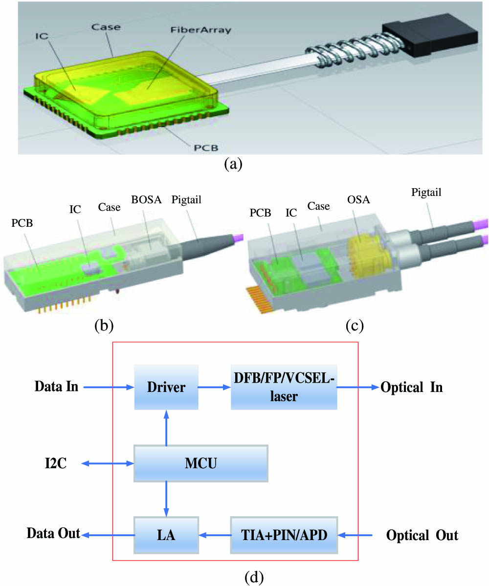
As we know, an optical transceiver is the main device to realize photoelectric conversion, and it is one of the most important devices in the optical-fiber data link system of aerocraft. In our Letter, we selected single-channel transceiver modules (HTS8566), parallel transmitter (HTA8567) and receiver (HTA8568) modules, and EPON OLT (HTS3261) and ONU (HTS2361) modules, which are produced by Hisense Corporation. The internal structure diagram of the selected optical transceivers is shown in Figs. 1(a)–1(c). The typical optical transceiver consists of a packaged semiconductor laser diode (LD) and photodetector, drive chips and microcontroller (MCU), etc. connected to a printed circuit board assembly (PCBA); Fig. 1(d) illustrates the chip relationship of each element of the selected transceivers[11].

Figure 1.Internal structure diagram of (a) parallel, (b) single-channel, (c) EPON, and (d) chip relationships of transceivers.
Based on the structure of the optical transceivers, the effects of irradiation on the LD and positive-intrinsic-negative (PIN) are mainly reflected by the ionization and DDD effects caused by various kinds of radiations and particles. The total dose effect will affect the performances of optoelectronic devices, such as lasers and detectors, which will cause the changing of dark current, bias voltage, and frequency response. As a result, the optical received power of the optical module is changed, and the bit error rate (BER) of the system is reduced.
The XC7K325T of the Xilinx Kintex-7 field-programmable gate array (FPGA) is used in the FPGA test system, and Fig. 2 illustrates the structure of the FPGA test system. According to the requirements of the experimental system, the FPGA system consists of three function modules, which are the optical transceivers module, voltage monitor module, and serial port module. (1) Optical transceivers are primarily responsible for sending and receiving pseudo-random binary sequence (PRBS) data, reading the inter-integrated circuit (I2C) messages of optical transceivers, and reporting the collected data to the serial port module. (2) The voltage monitor module records abnormal voltage and reports to the serial port module. The voltage monitor module can read real-time voltage by the ADS1258 chip, which is the voltage monitor chip by a serial peripheral interface (SPI) bus. When the voltage is abnormal, the alarming signal is read via the upper computer software. (3) The serial port module is the most fundamental module. The module receives the data from the other modules and sends the data in a sequence to the upper computer software by the interface of RS232 (Fig. 3).
Figure 2.FPGA block diagram of TID testing.
Figure 3.Function diagram of the TID testing board.
The function diagram of the TID testing board is shown in Fig. 3, and the performances of the optical transceivers are tested. In our testing, the test board is divided into two parts: the upper part is exposed to rays, and the lower part is shielded to avoid radiation effects. In the test board, M1#(HTA8567), M3# (HTA8568), M5#(HTS8566), M7#(HTS3261), and M9#(HTS2361) are the DUT, which are exposed to rays. M2#(HTA8568), M4#(HTA8657), M6#(HTS8566), M8#(HTS2361), and M10#(HTS3261) are the standard modules, which are shielded by the lead brick. Moreover, the communication process between optical transceivers is , , , , and .
The experiment is designed to identify the effects of -ray radiation on several commercial optical transceivers at increasing levels of absorbed doses of -ray radiation, which is shown in Fig. 4. Figure 4(a) shows the testing environment diagram of the TID. The TID test board was placed in a radiating room with a Co60 -ray source at a dose rate of 0.1 rad (Si)/s. In testing, the rise and fall of the Co60 -ray source is controlled by an external switch. When it rises, the test board is subjected to the radiation of Co60 sources, and when it lands, there is no radiation. The test board transfers the optical transceiver data to the computer through the serial port in the radiation room, and the standard modules (M2, M4, M6, M8, and M10) and the computer are shielded by the lead brick. The other computer, which is located outside the room, can observe the performances (such as the BER or real-time voltage) of the optical transceivers by remote control. Figure 4(b) shows the TID test device in the radiation room. Figure 4(c) shows the schematic diagram of the upper computer software; the BER, real-time voltage, I2C message of the optical transceivers are shown in the personal computer (PC) software.
Figure 4.Diagram of (a) the TID testing environment, (b) the TID test device, and (c) the upper computer software.
The current of each optical transceiver changes with the TID, as shown in Fig. 5. From the results, the current of HTA8568 and HTS8566 slightly changes and no bit error occurs during the whole process of TID testing. However, the current of HTA8567 and HTS2361 drops to 0.04 A and 0.03 A at 40 krad and 47 krad, respectively, and they will not work properly.
Figure 5.Current changing of optical modules with the TID.
Figure 6 shows the BER and other performances of optical transceivers via the upper computer software. Based on the results, there is no error bit of the HTA8567, HTA8568, and HTS8566 during the whole testing time. However, the bit error of the HTS3261 and HTS2361 modules occurs in the process of irradiation, and there is no bit error in the process of no radiation.
Figure 6.Schematic diagram of upper computer software.
Because HTS8566, HTS2361, and HTS3261 modules can be plugged from the test board, the receiver sensitivity of the three modules is tested, and the testing results are shown in Fig. 7. From the results, the receiver sensitivity of HTS3261 is decreased with an increase of the TID, about 2 dB from to . However, the receiver sensitivity of HTS8566 and HTS2361 is slightly changed and has about 1 dB fluctuation. The optical eye diagrams of HTS3261, HTS2361, and HTS8566 at different doses are shown in Fig. 8.
Figure 7.Receiver sensitivity of HTS2361, HTS3261, and HTS8566 at different total doses.
Figure 8.Eye diagram of (a), (b) HTS3261 at 0 and 50 krad, (c), (d) HTS2361 at 0 and 41 krad, and (e), (f) HTS8566 at 0 and 50 krad.
To explain the phenomenon of HTS3261 amd HTS2361, which occurs with bit error under irradiation and without bit error in no irradiation, we carried out the TID test again and positioned it in the same test environment.
In this testing, we used two test boards, one of which was identical to the one used in the first testing, and the other test board used EPON OLT/ONU+PIN components and EPON (no optical subassembly).
Figure 9 shows the changing current trend of the first test board with the TID in the second testing. The results of the second test are in agreement with the results of the first test; the HTA8568 and HTS8566 work well at all the testing time, and the HTA8567 and HTS2361 modules are not working normally around 40 and 47 krad, respectively. The bit error phenomenon of HTS3261 and HTS2361 is also consistent with the first testing; that is, there is bit error when irradiation exists, and there are no bit errors in the absence of radiation.
Figure 9.Current changing of the first test board with the total dose in the second testing.
For the high receiver sensitivity of EPON modules, the existing modules use avalanche photodiode (APD) detection. Therefore, to position the bit error reason of the EPON module, we change the APD to PIN detection and use the electric self-loopback. The current-changing trend of the results of the EPON and EPON is shown in Fig. 10. Based on the results, EPON shows bit error under irradiation and without bit error in no irradiation. However, there is no bit error for the EPON during the whole testing process. Therefore, the bit error phenomenon of the EPON OLT/ONU module is due to the problem of optical subassembly based on two testing results, and the optical subassembly in EPON is more sensitive to rays.
Figure 10.Current changing trend of the second board in the second TID testing.
In order to analyze the errors occurring from the EPON module, the structure of the optical subassembly and the influence of the -ray optical module are analyzed.
In the two TID tests, HTS8566 can work normally when the total dose is at 50 krad (Si), and there is no bit error in the whole irradiation process. Therefore, we compared and analyzed the optical subassembly of the EPON module (HTS3261) and HTS8566. Figure 10 shows the structure of the optical subassembly of the HTS3261 and HTS8566 modules. The bidirectional optical subassembly (BOSA) of HTS3261 consists of a distributed feedback (DFB) laser, isolator, APD, 0° optical filter, 45° beam splitter, and optical connection interface, which are shown in Fig. 11(a). However, the transmitting and receiving of the HTS8566 module takes a discrete form, which includes the receiver optical subassembly (ROSA) and transmitter optical subassembly (TOSA), which are shown in Figs. 11(b) and 11(c).
Figure 11.Structure of (a) BOSA of the HTS3261, (b) TOSA of HTS8566, and (c) ROSA of HTS8566.
After comparing the internal structure and materials of the HTS8566 and HTS3261 optical subassemblies, the main differences between the two optical subassemblies include the laser type [one DFB laser and the other Fabry–Perot (FP) laser], the isolator (EPON contains the isolator, and the HTS8566 does not contain), the detector type (EPON is APD, HTS8566 is PIN), and the beam-splitter (EPON contains beam-splitter, HTS8566 does not contain). Based on the second testing results, the sensitivity of the vertical-cavity surface-emitting laser (VCSEL) and FP laser to the radiation dose is not obvious, and the effect is reflected more in the change of efficiency and threshold. It is impossible to cause a small number of error bits, which can exclude the reason for the DFB laser. The beam splitter and the lens belong to the glass material, which can exclude the cause of the bit error. Subsequently, we find that the isolator of the HTS3261 optical subassembly contains Faraday magnetic media. The role of the isolator is to prevent the light reflected from the fiber from returning to the laser, and the jitter of the laser output power and the increase of the laser noise are prevented. Magnetic materials in the -ray environment and the indicators, such as permeability and magnetic field strength, will be changed[25,26]. In the isolator, the Faraday magnetic media are composed of a YIG single crystal, while the permeability of a single crystal of YIG would be disaccommodated in the -ray environment[27,28]. Therefore, the change of permeability affects the change of the crystal magnetic field, and the change of the magnetic field affects the filter function of the isolator, resulting in the occurrence of bit error.
For the irradiation performance of optical transceivers, we proposed the radiation reinforcement scheme for the low earth orbiting (LEO) and long-running aircraft (such as the International Space Station). The characteristics of the optical transceivers in the LEO environment are analyzed. Radiation performance of LEO aircraft mainly depends on such factors as protons, electrons, and bremsstrahlung. However, aluminum (Al) is one of the main measures used to shield these particles. Therefore, we obtained the effect of shielding particles of Al for 10 years by the irradiance analysis software Space Environment Information System (SPENVIS), which is shown in Fig. 12.
Figure 12.Relationship between the thickness of the Al shell and the 10-year dose of LEO aircraft.
Figure 12 shows the relationship between the thickness of the Al shell and the 10-year dose of LEO aircraft based on the SPENVIS software. From the simulation results, when the thickness of the Al shell is 1 mm, the total dose of radiation for 10 years is about 4.2 krad; when the thickness of the Al shell is 2 mm, the total dose of radiation is about 1.2 krad for 10 years; and the total dose is about 910 rad for 10 years when the thickness of the Al shell is 3 mm. Therefore, considering the size, weight, and irradiation effect of the optical transceivers, we recommend the use of an Al thickness of 2 mm for module reinforcement.
In summary, the TID performances of several commercial optical transceivers are tested via -ray radiation methods. The changing of current and receiver sensitivities of optical transceivers is discussed and analyzed when they are exposed to a TID of 50 krad (Si) at a dose rate of about 0.1 rad (Si)/s in the two-round TID tests. The results of the second test are in agreement with the results of the first test. The performance of single-channel transceivers and parallel receiving modules has not changed after 50 krad (Si) exposure, and the parallel transmitting and EPON ONU modules have not worked well after 40 krad (Si) and 47 krad (Si) exposure. Subsequently, we analyzed the reasons for the phenomenon of HTS3261/2361, which occurs as bit error under irradiation and without bit error in no irradiation, which is due to the magnetic medium in the isolator material of the HTS3261/HTS3261 optical subassembly. Finally, based on the theoretical analysis and testing results, this Letter provides design suggestions to improve the reliability for optical transceivers, which can be referenced by satellite system designation for various space missions.
References
[1] H. Kaushal, G. Kaddoum. IEEE Commun. Surv. Tutorials, 19, 57(2017).
[2] E. Sein, G. Planche, B. Laurent, J. P. Bouzinac, G. Oppenhauser, T. Tolker-Nielsen. Annales Des Télécommun., 58, 1849(2003).
[3] P. W. Marshall, C. J. Dale, K. A. LaBel. IEEE Trans. Nucl. Sci., 43, 645(1996).
[4] C. B. Kuznia, J. F. Ahadian, R. J. Pommer, R. Hagan. Proceedings of IEEE Radiation Effects Data Workshop, -92(2007).
[5] I. Arruego, J. Martínez, H. Guerrero. IEEE Trans. Nucl. Sci., 58, 3067(2011).
[6] F. Berghamans, M. Van Uffelen, A. F. Fernandez, B. Brichard, M. Decreton, A. Nowodzinski, A. Gusarov. Optical Fiber Communication Conference and Exhibit OFC, -1(2001).
[7] D. Kawase, H. Oomori, M. Shiozaki, H. Kurashima. SEI Technical Review Information & Communication, 73(2011).
[8] V. Heikkinen, T. Alajoki, E. Juntunen, M. Karppinen, K. Kautio, J.-T. Makinen, J. Ollila, J. Toivonen, R. Casey, S. Scott, W. Pintzka, S. Theriault, I. McKenzie. J. Lightwave Technol., 25, 1213(2007).
[9] S. Zeinolabedinzadeh, A. C. Ulusoy, F. Inanlou, H. Ying, Y. Gong, Z. E. Fleetwood, N. J. H. Roche, A. Khachatrian, D. McMorrow, S. P. Buchner, J. H. Warner. IEEE Trans. Nucl. Sci., 64, 536(2017).
[10] J. Jing, J. Liu, Y. Hou. Chin. Opt. Lett., 14, 030601(2016).
[11] Y. Zhan, S. Cao, Y. Wang, J. He. Optik, 138, 550(2017).
[12] Y. Zhan, S. Cao, Y. Wang, J. He. IEEE Avionics and Vehicle Fiber-Optics and Photonics Conference (AVFOP), -63(2017).
[13] A. H. Johnston. IEEE Trans. Nucl. Sci., 50, 689(2003).
[14] P. Stejskal. Radiation Effects in Optical Link Components for Future Particle Physics Detectors(2013).
[15] D. J. Cochran, S. D. Kniffin, K. A. LaBel, M. V. O’Bryan, R. A. Reed, R. L. Ladbury, J. W. Howard, C. Poivey, S. P. Buchner, C. J. Marshall, P. W. Marshall, H. S. Kim, D. K. Hawkins, M. A. Carts, J. D. Forney, A. B. Sanders, J. Bings, J. Seiler, N. E. Hall, T. Irwin, Z. Kahric, S. R. Cox, C. Palor. IEEE Radiation Effects Data Workshop, -57(2003).
[16] M. Bacha, A. Belghoraf. Chin. Opt. Lett., 15, 021301(2017).
[17] L. Ding, S. Gerardin, M. Bagatin, D. Bisello, S. Mattiazzo, A. Paccagnella. Nucl. Instrum. Methods Phys. Res. A, 796, 104(2015).
[18] M. Sajid, N. G. Chechenin, F. S. Torres, M. N. Hanif, U. A. Gulzari, S. Arslan, E. U. Khan. Nucl. Instrum. Methods Phys. Res. B, 428, 30(2018).
[19] H. J. Barnaby. IEEE Trans. Nucl. Sci., 53, 3103(2006).
[20] C. E. Barnes. Phys. Rev. B, 1, 4735(1970).
[21] A. V. Sogoyan, A. S. Artamonov, A. Y. Nikiforov, D. V. Boychenko. Electron. Energet., 27, 329(2014).
[22] Radiation Safety of Gamma, Electron and X Ray Irradiation Facilities(1992).
[23] W. Hua, G. Zhou, Y. Wang, P. Zhou, S. Yang, C. Peng, F. Bian, X. Li, J. Wang. Chin. Opt. Lett., 15, 033401(2017).
[24] Y. Yang, F. Yang. Chin. Opt. Lett., 14, 110605(2016).
[25] M. M. Sigalas, C. M. Soukoulis, R. Biswas, K. M. Ho. Phys. Rev. B, 56, 959(1997).
[26] J. A. Hodgson, T. P. Krichbaum, A. P. Marscher, S. G. Jorstad, B. Rani, I. Marti-Vidal, U. Bach, S. Sanchez, M. Bremer, M. Lindqvist, M. Uunila. Astron. Astrophys., 597, A80(2017).
[27] L. Torres, M. Zazo, J. Iniguez, C. De Francisco, J. M. Munoz, P. Hernandez. Appl. Phys. Lett., 68, 564(1996).
[28] K. Hisatake, I. Matsubara, K. Maeda, H. Wakao, T. Fujihara, Y. Kawai, K. Uematsu. J. Magn. Magn. Mater., 112, 387(1992).