
L. Martín, J. Benlliure, D. Cortina-Gil, J. Pe?as, C. Ruiz. Improved stability of a compact vacuum-free laser-plasma X-ray source[J]. High Power Laser Science and Engineering, 2020, 8(2): 02000e18
- High Power Laser Science and Engineering
- Vol. 8, Issue 2, 02000e18 (2020)
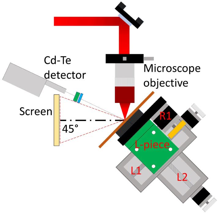
Fig. 1. Schematic representation of the setup where laser pulses are focused on a 1-mm-thick target by an  microscope objective. The X-rays produced are measured by a CdTe detector.
microscope objective. The X-rays produced are measured by a CdTe detector. ![Laser contrast measured with a third-order correlator with 60 fs steps and averaging 60 shots (TUNDRA, Ultrafast Innovations). The contrast obtained is at and at . Peaks located close to , and are artefacts produced by the measurement procedure while the real ones are the symmetrical postpulses with higher intensities[40].](/richHtml/hpl/2020/8/2/02000e18/img_2.png)
Fig. 2. Laser contrast measured with a third-order correlator with 60 fs steps and averaging 60 shots (TUNDRA, Ultrafast Innovations). The contrast obtained is  at
at  and
and  at
at  . Peaks located close to
  ,
,  and
and  are artefacts produced by the measurement procedure while the real ones are the symmetrical postpulses with higher intensities[40].
at and at . Peaks located close to , and are artefacts produced by the measurement procedure while the real ones are the symmetrical postpulses with higher intensities[40]. Fig. 3. Picture of the three stages of the target positioning system, the L-piece and the rotatory platform. The rotatory stage (R1) controls the angular coordinate, the upper linear stage (L1) controls the radial coordinate and the lower one (L2) controls the focal position.
Fig. 4. Laser focal spot obtained with the  microscope objective (
 ). By removing the target and using other microscope objective (
 ) we can image the focal spot as illustrated in the inset.
microscope objective (). By removing the target and using other microscope objective () we can image the focal spot as illustrated in the inset. Fig. 5. Speckle images obtained at different target positions. (a) 100 μm after focus, (b)  after focus, (c)
  after focus, (d)
  after focus, (e) speckle at focus, (f)
  before focus, (g)
  before focus, (h)
  before focus and (i)
  before focus. (j) Spectral intensity for low frequencies of the speckle pattern as a function of the target position with respect to the laser focus.
after focus, (c) after focus, (d) after focus, (e) speckle at focus, (f) before focus, (g) before focus, (h) before focus and (i) before focus. (j) Spectral intensity for low frequencies of the speckle pattern as a function of the target position with respect to the laser focus. Fig. 6. Integral of the X-ray energy spectra as a function of the distance to the nominal focus for laser pulses with  (red) and
  (blue).
(red) and (blue). Fig. 7. Map of the target surface deviations including the wobble effect.
Fig. 8. Example of two copper targets irradiated (a) with a constant angular velocity and (b) with a variable angular velocity.
Fig. 9. Five X-ray energy spectra measured, during 120 s each one, with the same laser conditions, but moving the target (a) with a constant angular velocity and (b) with a variable angular velocity according to the radius of the impact position. The colours represent spectra obtained in measurements done with different radial positions with respect to the target centre of rotation. The correction of the target offset with respect to focus was applied in all the measurements.
Fig. 10.  microscope image of the variable angular velocity target indicating the radii of the inner
  and the outer
  , the distance between craters
  and the radial distance between circles
  .
.
microscope image of the variable angular velocity target indicating the radii of the inner and the outer , the distance between craters and the radial distance between circles . Fig. 11. Total counts obtained at  in 24 different measurements of 3 min performed with two different targets and laser pulses of
  . Error bars are calculated as the systematic uncertainty in the determination of the solid angle of the collimator and the statistical uncertainty in X-ray counts.
in 24 different measurements of 3 min performed with two different targets and laser pulses of . Error bars are calculated as the systematic uncertainty in the determination of the solid angle of the collimator and the statistical uncertainty in X-ray counts. 
Set citation alerts for the article
Please enter your email address
© Copyright 2018-2021 | Chinese Laser Press. All Rights Reserved 沪ICP备15018463号-20