
L. Martín, J. Benlliure, D. Cortina-Gil, J. Pe?as, C. Ruiz. Improved stability of a compact vacuum-free laser-plasma X-ray source[J]. High Power Laser Science and Engineering, 2020, 8(2): 02000e18
- High Power Laser Science and Engineering
- Vol. 8, Issue 2, 02000e18 (2020)
Abstract
1 Introduction
X-rays are a very important tool for scientific research in physics, chemistry or biology. They have also become essential for a wide variety of societal applications, from nondestructive inspection for security or industry to medical imaging and treatment. These applications justify the present interest in developing compact, stable, micrometric size, high-average power and cost-effective sources as an alternative to conventional X-ray tubes and synchrotron-like facilities.
Advances in laser technology, such as chirped pulse amplification (CPA)[
In contrast, for solid targets and intensities larger than
Sign up for High Power Laser Science and Engineering TOC. Get the latest issue of High Power Laser Science and Engineering delivered right to you!Sign up now
Bremsstrahlung laser-plasma sources are made from a wide variety of metallic solid targets, i.e., Cu, Mo, Ag, Sn, Al and Ta, or nonmetallic ones like Si or Ge. Moreover, they can be built in different arrangements that include rotating disks[
The X-ray radiation produced by laser-plasma sources is pulsed with a duration comparable to the laser pulses. Depending on the laser and target parameters, laser-plasma sources with bunches from tens of femtosecond to few picoseconds have been measured or estimated[
Laser-driven X-ray sources with moderate laser pulse energies (
In order to produce laser-driven X-ray sources using laser systems with high repetition rates (1–10 kHz) and moderate energies (1–10 mJ) where the focalization is tight, it is necessary to overcome three main challenges: Replenishing the target material after each impact. Repositioning the target with respect to the laser focus with high precision to keep constant the laser pulse intensity on target, using a set of target position diagnostics and movement acting during the continuous operation of the source. Designing a target assembly providing the two previous functions at a kHz pulse repetition rate.
To the best of our knowledge, one of the few laser-induced X-ray sources fulfilling these requirements was built by Zamponi and collaborators[
2 Table-top X-ray source
The laser-plasma X-ray source presented in this work is based on the interaction of infrared laser pulses, focused on a very small spot[
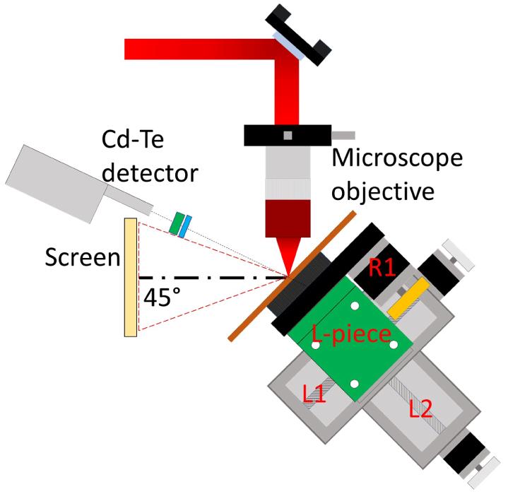
In our experiment, ultrashort infrared laser pulses are focused on a 1-mm-thick copper plate target to produce backward emitted X-ray pulses. Figure
We used the low energy line of the laser system (THALES ALPHA 10/XS, 1 mJ, 35 fs, 1 kHz, 800 nm) installed at the Laser Laboratory for Acceleration and Applications (L2A2) at the University of Santiago de Compostela (USC)[
The measurement of the duration of the
The X-ray energy spectra were measured with a CdTe detector (Amptek, XR-100T-CdTe) calibrated using the standard procedure[
A laser-driven X-ray source running in air provides clear practical advantages. The technical requirements for vacuum operation are not present and therefore the operation is easier. Moreover, it provides flexibility for its use in imaging, as the locations of the source and the detectors are not restricted by the dimensions of a vacuum chamber. The electrons emitted by the source are stopped in air within some few millimetres and there is no need to introduce a deflecting magnet. Also, the contamination of the optics due to the debris is lower than in the case of operation in vacuum.
This laser-driven X-ray source also presents drawbacks as the nonlinear propagation of the laser pulses in air from the exit of the microscope objective to the target. This requires a careful calibration of the displacement of the focal position and complicates the estimation of the laser intensity on target.
3 Target positioning system
The main challenges for this type of X-ray source is to renew the target material at the impact position while keeping the target on focus at kHz repetition rate. This is achieved by a target positioning system that takes into account both, the size of the affected area at the target surface after each shot and the magnitude of the Rayleigh length for the focusing conditions. The target area affected depends on the intensity and incident angle of the laser pulses. In this focusing geometry the Rayleigh range is on the order of a few microns requiring precise positioning of the target to maintain high intensities.
The target positioning system developed in this work is composed by two identical linear stages L1 and L2 (PiMicos, VT-80) and a rotatory stage R1 (PiMicos, DT-50), where L1 and L2 (Figure
Several solutions for the target positioning system in this kHz regime are reported in literature[
The stability, high-average power, and long periods of operation of the X-ray source are determined by the movements of the target positioning system. To optimize the performances of the source, advanced diagnostic systems to characterize the focal position and a precise definition of the target movement are needed.
4 Focusing diagnostics
The characterization of the laser focus is critical for the optimum operation of the X-ray source. In particular, we need to measure the laser spot size at the focal position of the microscope objective, in order to estimate the intensity of the laser pulses at focus, knowing also the pulse duration and energy. In this section, we present a set of well-known diagnostics to determine the focus size, the focus position in the linear regime and the shift of the focus due to the nonlinear effects induced by the propagation in air.
The laser focus is imaged with a calibrated system composed by a microscope objective (Mitutoyo, M Plan APO NIR
The precise positioning of the target is of utmost importance for optimizing the stability of the X-ray source. For this purpose, we used the speckle technique based on the observation of the laser specular reflection on the target[
Figure
The pulse intensities attained before focus are enough to ionize air and to induce nonlinear effects during the pulse propagation. The competition between the two main nonlinear effects at these intensities, self-phase modulation and auto-focusing (Kerr effect)[
Maintaining the pulse duration and the spot size constant, we were able to characterize this focus displacement in terms of the pulse energy. For a fixed detection angle (
5 Target movement optimization
The stability and repeatability of the X-ray source relies on the optimization of the target assembly movement to refresh the target material shot by shot and to position the target at laser focus position. Two important issues concerning this movement should be considered. The first one is related to the wobble of the target, due to the tilt of the axis of the rotating stage holding the target material while it is moving. The second one is the distance between impact positions on the target surface for consecutive laser shots at 1 kHz repetition rate.
We applied two different corrections to address these issues and to guarantee the stability of the source. The first one is the modification of the angular velocity according to the radial position of the impacts. The second is the longitudinal displacement of the target surface with respect to the focal position of the laser pulses or target offset.
The wobble caused by the fast movement of the rotating stage will modify the position of the target surface with respect to the laser focus. According to the manufacturer specifications the wobble of the rotatory stage used in the present target assembly is
The second important issue affecting the repeatability of the X-ray source is the angular velocity of the target. This angular velocity defines, together with the radius, the linear velocity of any point at the target surface. The separation between impacts at the target surface is thus an important parameter for the stability and optimization of the X-ray source[
Two strategies concerning the angular velocity are possible. The first one is to keep the angular velocity constant, resulting in smaller separations between laser impacts while decreasing the radius. In Figure
The second strategy consists on using a variable angular velocity movement, optimized by choosing a fixed distance between impacts and, accommodating the movement of the whole system to the irradiation radius. To optimize this movement, one should consider the size of the holes at the target surface produced by a single shot. Measurements of the holes produced by the laser pulses with a scanning electron microscope show a deep crater of around
Based on these measurements, we chose
The motions of the motors refresh the target material and correct the target position with respect to focus. At 1 kHz the correction of the position of the target with respect to focus cannot be done shot by shot; alternatively, we choose to implement this correction at four equidistant points for each circle. First, the target rotates
Figure
The operation of the target with a constant angular velocity is simpler, because it is not necessary to know the impact radius. However, in order to reach a stable operation in this mode, it would be necessary to use larger targets to avoid overlap between impacts. On the other hand, adjusting the angular speed as a function of the impact radius allows us to define a smaller fixed separation distance between laser impacts. This optimization of the target positioning allows us to maximize the number of laser impacts per target and to maintain continuous operation for as long as 36 min with very good stability. This operation time could be increased by using larger targets.
6 Results
The variable angular velocity operation mode presented in Section
The final stability of the source can be quantified in terms of the repeatability of the characteristics of the produced X-rays. To investigate this repeatability we have measured 24 X-ray spectra at
We quantified the stability of the X-ray source by looking to the variations of the X-ray flux in different measurements, which amounts to
Another important parameter defining the potential use of this kind of X-ray sources in different applications is the delivered dose rate. We measured the dose delivered by the source described in this work using ring-type TLDs (Harshaw, TLD-100). The dose rate we have obtained amounts to
We can then conclude that this is a cost-effective source delivering
7 Conclusions
In this paper, we have presented a table-top laser-plasma X-ray source in a vacuum-free environment based on solid targets. We have also investigated the three main parameters affecting the stability of this source: focus location, focus shift by self-focusing and target positioning and movement.
The speckle technique allows us to determine the nominal focus position and to calibrate the focus shift due to the nonlinear effects induced by the propagation of the laser pulse in air. The precise determination of the focus shift in air is important to maximize the X-ray dose of this source.
The target movement optimization using a variable angular velocity mode is crucial to obtain the stable operation of the source in terms of flux and X-ray spectrum. This strategy allows us to avoid the overlap of laser impacts on the target surface while maximizing the use of the target surface and obtaining a repeatability better than 93% for nonstop operation time as long as 36 min per target. This operation time could be easily increased by using targets with larger surfaces.
Moreover, this source belongs to a family of X-ray sources with unique characteristics such as sub-picosecond X-ray pulses at kHz repetition rates and micrometric source size. These characteristics make it suitable for X-ray time-resolved experiments and high-resolution imaging techniques like phase contrast as important applications in chemistry, biology and medicine.
References
[1] D. Strickland, G. Mourou. Opt. Commun., 56, 219(1985).
[2] T. Brabec, F. Krausz. Rev. Mod. Phys., 72, 545(2000).
[3] P. Gibbon, E. Förster. Plasma Phys. Control. Fusion, 38, 769(1996).
[4] S. Corde, K. T. Phuoc, G. Lambert, R. Fitour, V. Malka, A. Rousse, A. Beck, E. Lefebvre. Rev. Mod. Phys., 85, 1(2013).
[5] A. Döpp, E. Guillaume, C. Thaury, A. Lifschitz, F. Sylla, J.-P. Goddet, A. Tafzi, G. Iaquanello, T. Lefrou, P. Rousseau, E. Conejero, C. Ruiz, K. Ta Phuoc, V. Malka. Nucl. Instrum. Methods Phys. Res. Sec. A: Accel. Spectr. Detect. Assoc. Equip., 830, 515(2016).
[6] F. Brunel. Phys. Rev. Lett., 59, 52(1987).
[7] P. Gibbon, A. R. Bell. Phys. Rev. Lett., 68, 1535(1992).
[8] P. K. Singh, Y. Q. Cui, A. Adak, A. D. Lad, G. Chatterjee, P. Brijesh, Z. M. Sheng, G. R. Kumar. Sci. Rep., 5, 17870(2015).
[9] W. Kruer, K. Estabrook. Phys. Fluids, 28, 430(1985).
[10] L. M. Chen, P. Forget, S. Fourmaux, J. C. Kieffer, A. Krol, C. C. Chamberlain, B. X. Hou, J. Nees, G. Mourou. Phys. Plasmas, 11, 4439(2004).
[11] J. C. Kieffer, S. Fourmaux, A. Krol. Proc. SPIE, 10226(2017).
[12] K. Huang, M. H. Li, W. C. Yan, X. Guo, D. Z. Li, Y. P. Chen, Y. Ma, J. R. Zhao, Y. F. Li, J. Zhang, L. M. Chen. Rev. Sci. Instrum., 85(2014).
[13] A. Sjögren, M. Harbst, C.-G. Wahlström, S. Svanberg, C. Olsson. Rev. Sci. Instrum., 74, 2300(2003).
[14] M. Hagedorn, J. Kutzner, G. Tsilimis, H. Zacharias. Appl. Phys. B, 77, 49(2003).
[15] F. Gobet, F. Hannachi, M. M. Aléonard, J. F. Chemin, G. Claverie, M. Gerbaux, G. Malka, J. N. Scheurer, M. Tarisien, F. Blasco, D. Descamps, F. Dorchies, R. Fedosejevs, C. Fourment, S. Petit, V. Méot, P. Morel, S. Hanvey, L. Robson, B. Liesfeld. Rev. Sci. Instrum., 77(2006).
[16] C. G. Serbanescu, R. Fedosejevs. Appl. Phys. B, 83, 521(2006).
[17] M. Li, K. Huang, L. Chen, W. Yan, M. Tao, J. Zhao, Y. Ma, Y. Li, J. Zhang. Radiat. Phys. Chem., 137, 78(2017).
[18] N. Zhavoronkov, Y. Gritsai, M. Bargheer, M. Woerner, T. Elsaesser. Appl. Phys. Lett., 86(2005).
[19] H. Witte, M. Silies, T. Haarlammert, J. Hüve, J. Kutzner, H. Zacharias. Appl. Phys. B, 90, 11(2008).
[20] M. Silies, H. Witte, S. Linden, J. Kutzner, I. Uschmann, E. Förster, H. Zacharias. Appl. Phys. A, 96, 59(2009).
[21] F. Zamponi, Z. Ansari, C. v. K. Schmising, P. Rothhardt, N. Zhavoronkov, M. Woerner, T. Elsaesser, M. Bargheer, T. Trobitzsch-Ryll, M. Haschke. Appl. Phys. A, 96, 51(2009).
[22] J. Weisshaupt, V. Juvé, M. Holtz, S. Ku, M. Woerner, T. Elsaesser, S. Ališauskas, A. Pugžlys, A. Baltuška. Nat. Photon., 8, 927(2014).
[23] Y. Jiang, T. Lee, W. Li, G. Ketwaroo, C. G. Rose-Petruck. Opt. Lett., 27, 963(2002).
[24] A. Bonvalet, A. Darmon, J.-C. Lambry, J.-L. Martin, P. Audebert. Opt. Lett., 31, 2753(2006).
[25] G. Korn, A. Thoss, H. Stiel, U. Vogt, M. Richardson, T. Elsaesser, M. Faubel. Opt. Lett., 27, 866(2002).
[26] B. Hou, J. Nees, A. Mordovanakis, M. Wilcox, G. Mourou, L. M. Chen, J.-C. Kieffer, C. C. Chamberlain, A. Krol. Appl. Phys. B, 83, 81(2006).
[27] B. Hou, J. Easter, A. M. K. Krushelnick, J. A. Nees. Opt. Express, 16, 17695(2008).
[28] S. Inoue, S. Tokita, K. Otani, M. Hashida, M. Hata, H. Sakagami, T. Taguchi, S. Sakabe. Phys. Rev. Lett., 109(2012).
[29] T. Feurer, A. Morak, I. Uschmann, C. Ziener, H. Schwoerer, C. Reich, P. Gibbon, E. Förster, R. Sauerbrey, K. Ortner, C. R. Becker. Phys. Rev. E, 65(2001).
[30] C. Rischel, A. Rousse, I. Uschmann, P.-A. Albouy, J.-P. Geindre, P. Audebert, J.-C. Gauthier, E. Förster, J.-L. Martin, A. Antonetti. Nature, 390, 490(1997).
[31] A. Cavalleri, C. W. Siders, F. L. H. Brown, D. M. Leitner, C. Tóth, J. A. Squier, C. P. J. Barty, K. R. Wilson, K. Sokolowski-Tinten, M. H. von Hoegen, D. von der Linde, M. Kammler. Phys. Rev. Lett., 85, 586(2000).
[32] M. Bargheer, N. Zhavoronkov, Y. Gritsai, J. C. Woo, D. S. Kim, M. Woerner, T. Elsaesser. Science, 306, 1771(2004).
[33] B. Hou, J. A. Nees, W. Theobald, G. A. Mourou, L. M. Chen, J.-C. Kieffer, A. Krol, C. C. Chamberlain. Appl. Phys. Lett., 84, 2259(2004).
[34] C. G. Serbanescu, J. A. Chakera, R. Fedosejevs. Rev. Sci. Instrum., 78, 103502(2007).
[35] B. Hou, A. Mordovanakis, J. Easter, K. Krushelnick, J. A. Nees. Appl. Phys. Lett., 93, 201503(2008).
[36] G. H. McCall. J. Phys. D Appl. Phys., 15, 823(1982).
[37] D. Salzmann, C. Reich, I. Uschmann, E. Förster, P. Gibbon. Phys. Rev. E, 65, 036402(2002).
[38] J. Galy, M. Maučec, D. J. Hamilton, R. Edwards, J. Magill. New J. Phys., 9, 23(2007).
[39] J. Benlliure, D. Cortina-Gil, J. J. Llerena, C. Ruiz. Nucl. Instrum. Methods Phys. Res. Sect. A, 916, 158(2019).
[40] D. Herrmann, L. Veisz, R. Tautz, F. Tavella, K. Schmid, V. Pervak, F. Krausz. Opt. Lett., 34, 2459(2009).
[41] W. Wang, J. Liu, Y. Cai, C. Wang, L. Liu, C. Xia, A. Deng, Y. Xu, Y. Leng, R. Li, Z. Xu. Phys. Plasmas, 17, 023108(2010).
[42] M. Cerchez, R. Jung, J. Osterholz, T. Toncian, O. Willi, P. Mulser, H. Ruhl. Phys. Rev. Lett., 100, 245001(2008).
[43] N. Tisnek, E. Kalanxhi, C. W. Serkland, J. Iversen, O. V. Belyakov, J. Dahle. Appl. Radiat. Isot., 67, 1998(2009).
[44] G. Hernández, F. Fernández. Appl. Phys. B, 124, 119(2018).
[45] H. Legall, G. Blobel, H. Stiel, W. Sandner, C. Seim, P. Takman, D. H. Martz, M. Selin, U. Vogt, H. M. Hertz, D. Esser, H. Sipma, J. Luttmann, M. Höfer, H. D. Hoffmann, S. Yulin, T. Feigl, S. Rehbein, P. Guttmann, G. Schneider, U. Wiesemann, M. Wirtz, W. Diete. Opt. Express, 20, 18362(2012).
[46] N. Zhang, X. Zhu, J. Yang, X. Wang, M. Wang. Phys. Rev. Lett., 99, 167602(2007).
[47] L. Martín, J. Benlliure, D. Cortina, J. J. Llerena, D. González, C. Ruiz. J. Phys.: Conf. Ser., 1079, 012008(2018).
[48] D. Carroll, P. McKenna, S. Kar, M. Borghesi, P. Foster, D. Symes, R. Pattathil, D. Neely. , CLF Annual Report (2012)..
[49] D. Carroll, M. Coury, G. Scott, P. Mckenna, M. Streeter, H. Nakamura, Z. Najmudin, F. Fiorini, S. Green, J. Green. , CLF Annual Report (2011)..
[50] A. Couairon, A. Mysyrowicz. Phys. Rep., 441, 47(2007).
[51] K. Lim, M. Durand, M. Baudelet, M. Richardson. Sci. Rep., 4, 7217(2015).
[52] A. A. Dergachev, A. A. Ionin, V. P. Kandidov, D. V. Mokrousova, L. V. Seleznev, D. V. Sinitsyn, E. S. Sunchugasheva, S. A. Shlenov, A. P. Shustikova. Laser Phys. Lett., 12, 015403(2015).
[53] A. Talebpour, S. Petit, S. Chin. Opt. Commun., 171, 285(1999).
[54] Y. Hironaka, Y. Fujimoto, K. G. Nakamura, K.-I. Kondo, M. Yoshida. Appl. Phys. Lett., 74, 1645(1999).

Set citation alerts for the article
Please enter your email address
© Copyright 2018-2021 | Chinese Laser Press. All Rights Reserved 沪ICP备15018463号-20