
Shaobo Fang, Zhiyi Wei. Sub-Optical-Cycle Coherent Waveform Synthesis[J]. Acta Optica Sinica, 2019, 39(1): 0126006
- Acta Optica Sinica
- Vol. 39, Issue 1, 0126006 (2019)
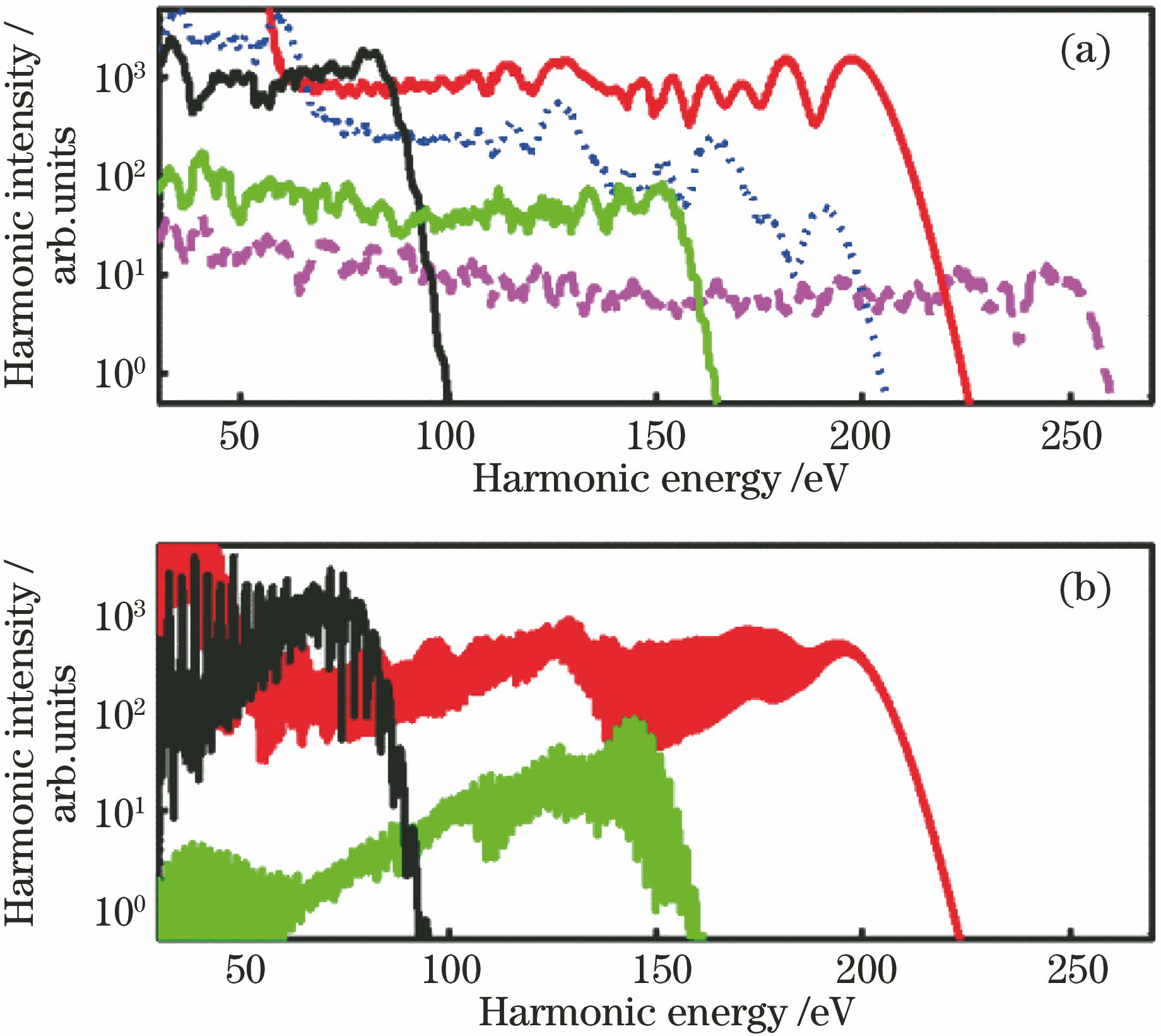
Fig. 1. High-order harmonic spectrum (red) driven by sub-periodic “perfect” waveform.(a) Single active electron calculations;(b) full propagation calculations
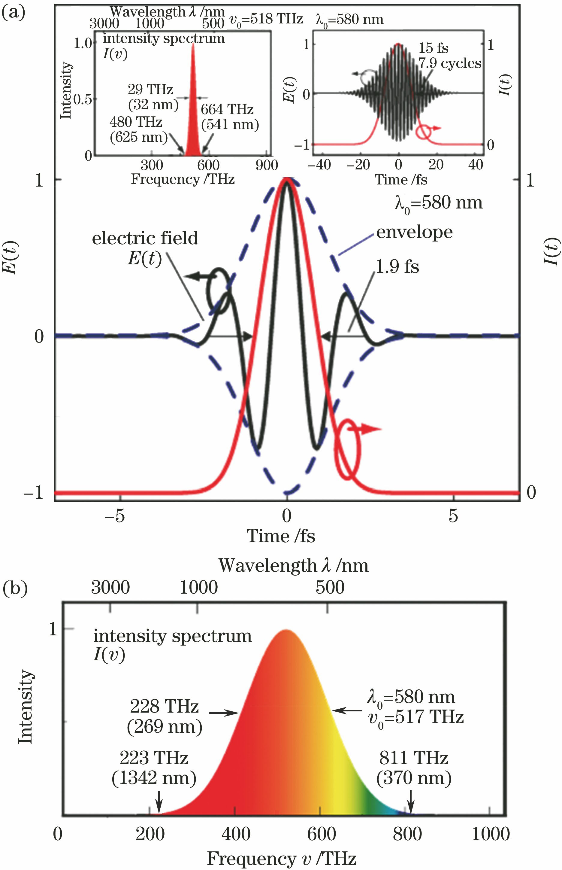
Fig. 2. Time-frequency domain relationship of Fourier transform limit pulses. (a) Mono-cycle pulse in time domain (inset: multi-cycle pulse in time and frequency domain); (b) mono-cycle pulse in frequency domain
Fig. 3. Supercontinuum generated by self-phase modulation
Fig. 4. Supercontinuum generated by induced-phase modulation
Fig. 5. Multiple-thin-plate generated femtosecond supercontinuum
Fig. 6. (a) Layout diagram of seven fused silica thin plates and (b) supercontinuum after the laser beam propagated through seven fused silica thin plates (inset: the output beam profile taken at the collimating mirror; the center peak is saturated to show the structures of the rings)
Fig. 7. Passively CEP-stabilized white-light seed continuum generated in a YAG crystal pumped by the CEP-stable idler pulses[2,44]. (a) Supercontinuum spectrum; (b) photo of the experiment setup
Fig. 8. Structural schematics. (a) Prism pair compressor; (b) grating pair compressor
Fig. 9. Schematic structure of chirped mirror
Fig. 10. Pulse shaping system schematic based on spatial light modulator
Fig. 11. Synthesized electric field influenced by carrier-envelope phase and relative-envelope phase
Fig. 12. CEP- and REP-controlled synthesized electric fields. (a) The optimum configuration, corresponding to the shortest synthesized waveform, and being a reference for the other configurations; (b) pure CEP slip by a quarter of the optical cycle; (c) delay of the pulse by a quarter of the optical cycle; (d) pure delay of the envelope by a quarter of the optical cycle
Fig. 13. (a) BOC scheme diagram and (b) locking range
Fig. 14. Schematic and accuracy of spectral interference lock delay. (a) Schematic of the transient grating FROG apparatus; (b) temporal overlap to yield a single spectral fringe; (c) supercontinuum
Fig. 15. (a) Schematic and (b) accuracy of spectral interference lock delay

Set citation alerts for the article
Please enter your email address
© Copyright 2018-2021 | Chinese Laser Press. All Rights Reserved 沪ICP备15018463号-20