
Tao Li, Kaibo Xia, Naifei Ren, Fuqiang Gao, Wen Zhang, Jianan Tian, Yongsheng Fan. Study on Pulse Laser Drilling Based on Improved Parameter Control Method[J]. Laser & Optoelectronics Progress, 2020, 57(19): 191403
- Laser & Optoelectronics Progress
- Vol. 57, Issue 19, 191403 (2020)
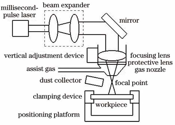
Fig. 1. Schematic of millisecond pulse laser drilling system
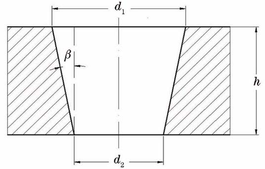
Fig. 2. Calculation of via-hole taper
Fig. 3. Schematic of penetration detection principle. (a) Schematic of detection device; (b) schematic of pulse signal
Fig. 4. Influence of defocusing amount on entrance and end diameters of via-hole
Fig. 5. Influence of defocusing amount on threshold of pulse number
Fig. 6. Cross sections and taper a change of via-hole drilled under different defocusing amounts. (a) -2.8 mm; (b) -1.8 mm; (c) 0.8 mm; (d) 0 mm; (e) 0.8 mm; (f) 1.8 mm; (g) 2.8 mm; (h) taper change of via-hole
Fig. 7. Schematic of beam expansion ratio
Fig. 8. Influence of beam expanding ratio on entrance and end diameters of via-hole
Fig. 9. Influence of beam expanding ratio on threshold of pulse number
Fig. 10. Cross sections and taper change of via-hole drilled under different beam expanding ratios. (a) 1; (b) 1.8; (c) 2.8; (d) 3.8; (e) 4.8; (f) 5.8;(g) taper change of via-hole
Fig. 11. Experimental results of drilling holes in argon
Fig. 12. Influence of pulse repetition frequency on entrance and end diameters of via-hole
Fig. 13. Influence of pulse repetition frequency on threshold of pulse number
Fig. 14. Cross sections and taper change of via-hole drilled under different pulse repetition frequencies. (a) 15 Hz; (b) 25 Hz; (c) 35 Hz; (d) 45 Hz; (e) 65 Hz; (f) 85 Hz; (g) 100 Hz;(h) taper change of via-hole
|
Table 1. Chemical composition of nickel-based superalloy GH4037
|
Table 2. Improved control variable method
| |||||||||||||||||||||||||||||||||||||||
Table 3. Comparison of drilling efficiency between improved control variable method and traditional control variable method under different defocusing amounts
| |||||||||||||||||||||||||||||||||||||||
Table 4. Comparison of drilling efficiency between improved control variable method and traditional control variable method under different beam expanding ratios
| |||||||||||||||||||||||||||||||||||||||
Table 5. Comparison of drilling efficiency between improved control variable method and traditional control variable method under different pulse repetition frequencies

Set citation alerts for the article
Please enter your email address
© Copyright 2018-2021 | Chinese Laser Press. All Rights Reserved 沪ICP备15018463号-20