
An Shu, Haodong Pei, Lei Ding, Huixian Duan, Shanshan Zhou. Binocular Visual Position and Attitude Measurement Method for a Spatial Non-Cooperative Target[J]. Acta Optica Sinica, 2020, 40(17): 1712003
- Acta Optica Sinica
- Vol. 40, Issue 17, 1712003 (2020)
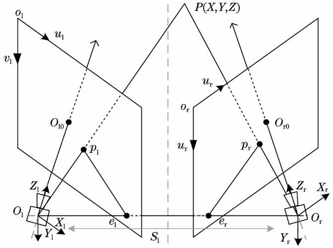
Fig. 1. Binocular visual position and attitude measurement model
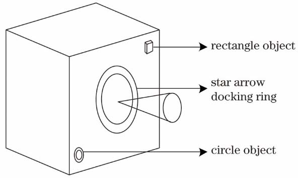
Fig. 2. Non-cooperative target structure simulation diagram
Fig. 3. Schematic of docking ring detection of left images. (a) Set of candidate ellipses; (b) bounding ellipse by filtered
Fig. 4. Schematic of docking ring detection of right images. (a) Set of candidate ellipses; (b) bounding ellipse by filtered
Fig. 5. Two-pass algorithm diagram. (a) Primary pass; (b) secondary pass
Fig. 6. Detection of circular marking points. (a) Connected regions by two-pass algorithm; (b) regions with area constraints;(c) regions with curvature constraints; (d) geometric centers of the regular marking points
Fig. 7. Pose diagram of the target coordinate system and the left camera coordinate system
Fig. 8. Binocular visual measurement platform diagram
Fig. 9. Position and attitude in experiment 1. (a)(b)(c) Absolute positions of x, y and z axes; (d)(e)(f) absolute angles of x, y and z axes; (g)(h) relative positions and angles of three axes
Fig. 10. Position and attitude in experiment 2. (a)(b)(c) Absolute positions of x, y and z axes; (d)(e)(f) absolute angles of x, y and z axes; (g)(h) relative positions and angles of three axes
Fig. 11. Position and attitude in experiment 3. (a)(b)(c) Absolute positions of x, y and z axes; (d)(e)(f) absolute angles of x, y and z axes; (g)(h) relative positions and angles of three axes

Set citation alerts for the article
Please enter your email address
© Copyright 2018-2021 | Chinese Laser Press. All Rights Reserved 沪ICP备15018463号-20