
Chunlei Yu, Haimei Gong, Xue Li, Songlei Huang, Bo Yang, Xianliang Zhu, Xiumei Shao, Tao Li, Yi Gu. 2560×2048 short-wave infrared InGaAs focal plane detector (Invited)[J]. Infrared and Laser Engineering, 2022, 51(3): 20210941
- Infrared and Laser Engineering
- Vol. 51, Issue 3, 20210941 (2022)
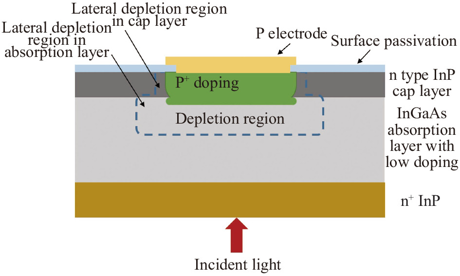
Fig. 1. Profile structure of planar In0.53Ga0.47As detector

Fig. 2. C -V curve of detectors with different doping absorption layers
Fig. 3. Dark current density of InGaAs detectors with different sizes
Fig. 4. Relationship between dark current density and P /A
Fig. 5. Dark current density of different pitch array devices at room temperature
Fig. 6. Change of chip flatness with the increase of balance film thickness
Fig. 7. Influence of the morphology and consistency of the indium pillar bumps on the connectivity rate
Fig. 8. Indium bump growth process. (a) Original process; (b) Improved process
Fig. 9. Indium bump arrays fabricated via the modified SiNx recipe: SEM images for 15 μm pitch (a) before and (b) after reflow, and 10 μm pitch (c) before and (d) after reflow; (e) and (f) Statistical diameter distribution of the ball arrays for 15 μm pitch and 10 μm pitch respectively
Fig. 10. Hybridization of focal plane
Fig. 11. Response spectra curve of 2560×2048 InGaAs focal plane arrays
Fig. 12. Measured result of response signal of FPAs. (a) Pixel signal map; (b) Signal statistical distribution
Fig. 13. Measured result of noise of FPAs. (a) Pixel noise map; (b) Noise statistical distribution
Fig. 14. Imaging verification using HDR technology
Fig. 15. Imaging verification of 10 μm pitch 2560×2048 InGaAs focal plane arrays
Fig. 16. Comparison of the details of visible and short-wave infrared imaging
Fig. 17. 10 μm pitch 2560×2048 InGaAs focal plane arrays. (a) Photosensitive chip; (b) Readout circuit; (c) Focal plane
|
Table 1. Test conditions of 2560×2048 InGaAs focal plane arrays


Set citation alerts for the article
Please enter your email address

© Copyright 2018-2021 | Chinese Laser Press. All Rights Reserved 沪ICP备15018463号-20