
Zhao CHEN, Yingjie XIAO, Pengcheng ZHAO, Liangxing PENG. Research on effective temperature calculation method of annular fuel cell[J]. NUCLEAR TECHNIQUES, 2022, 45(12): 120603
- NUCLEAR TECHNIQUES
- Vol. 45, Issue 12, 120603 (2022)
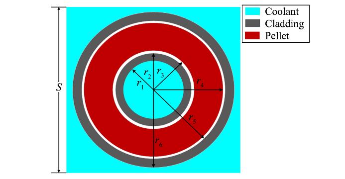
Fig. 1. Schematic diagram of annular fuel rod structure (
r1=4.316 5 mm,
r2=4.888 0 mm,
r3=4.950 0 mm,
r4=7.050 0 mm,
r5=7.112 0 mm,
r6=7.683 5 mm,
S=16.51 mm)
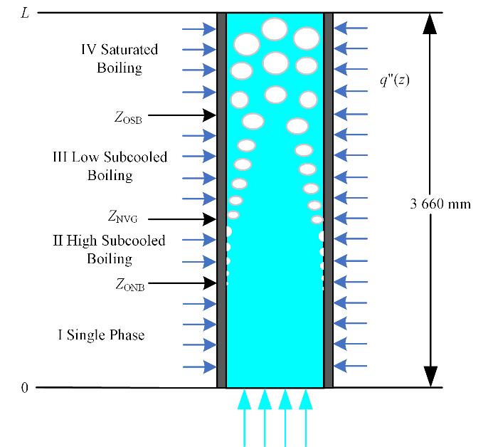
Fig. 2. Heat transfer partition diagram of heated channel
Fig. 3. Flow chart of THCAFS code
Fig. 4. Comparison of annular fuel thermal hydraulic code (a) Heat transfer coefficient of inner channel, (b) Heat transfer coefficient of outer channel, (c) DNBR of inner channel, (d) DNBR of outer channel
Fig. 5. Verification of the temperature field of fuel cell at the hot spot
Fig. 6. Flow chart for solving effective temperature of annular fuel cell
Fig. 7. Refined modeling of annular fuel cell
Fig. 8. Radial node division of annular fuel
Fig. 9. Radial power distribution under different burnups
Fig. 10. Changes of nuclide density under different burnups
Fig. 11. Fitting of polynomial coefficients
a(
x),
b(
x) and
c(
x)
Fig. 12. Ratio of fitting function value to simulation value under different burnup
Fig. 13. Temperature field of fuel cell at the hot spot (40 MWd·kgHM-1)
Fig. 14. Calculation of effective temperature for fuel cell at the hot spot (40 MWd·kgHM-1)
| |||||||||||||||||||||||||||||
Table 1. Verification of mass flow and pressure drop


Set citation alerts for the article
Please enter your email address

© Copyright 2018-2021 | Chinese Laser Press. All Rights Reserved 沪ICP备15018463号-20