
Yu Lei, Fang Guo. Dual-mode camera using liquid-crystal microlens for high-resolution three-dimensional reconstruction[J]. Infrared and Laser Engineering, 2020, 49(8): 20190540
- Infrared and Laser Engineering
- Vol. 49, Issue 8, 20190540 (2020)
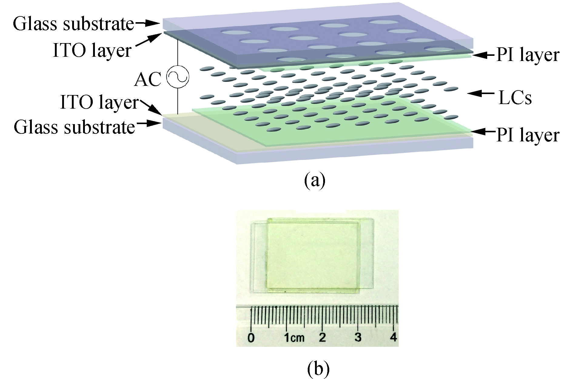
Fig. 1. LCMLA device. (a) 3D structure (not in scale) and (b) an actual LCMLA with two conductive tapes
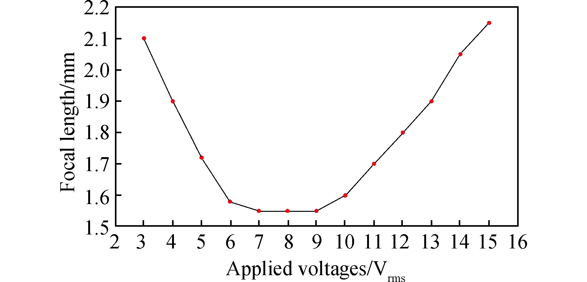
Fig. 2. Focal length vs the signal voltage applied over the LCMLA fabricated by us
Fig. 3. Layout of the DMC (not in scale)
Fig. 4. DMC prototype
Fig. 5. Elemental images acquired when the aperture is, (a) small, (b) suitable, and (c) large
Fig. 6. Typical imaging process of the DMC prototype constructed
Fig. 7. Partial image space of the main lens system that is behind the LCMLA (not in scale)
Fig. 8. Plenoptic images. (a) Panorama image, (b) a close-up of the far brick, (c) a close-up of the middle brick, and (d) a close-up of the near brick
Fig. 9. Typical imaging character of the planar imaging mode including: (a) far brick, (b) middle brick, and (c) near brick
Fig. 10. Parameter arrangement for the depth estimation of 3D reconstruction
Fig. 11. Window matching between two adjacent microlenses
Fig. 12. Parameter configuration for 3D positioning
Fig. 13. Image matching between two imaging modes. (a) Patch of the near brick and (b) matching clip of the planar image
Fig. 14. High-resolution 3D pattern reconstruction of the three bricks

Set citation alerts for the article
Please enter your email address
© Copyright 2018-2021 | Chinese Laser Press. All Rights Reserved 沪ICP备15018463号-20