
Hongyu Li, Lianfeng Wei, Zeming Wang, Hui Chen, Na Zheng, Ran Zhang, Wei Wang. Thermal Fatigue Properties of Laser Cladding Fe-Based Coating[J]. Laser & Optoelectronics Progress, 2021, 58(7): 0714003
- Laser & Optoelectronics Progress
- Vol. 58, Issue 7, 0714003 (2021)
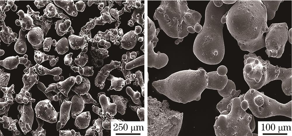
Fig. 1. Microstructures of Lc-Sr-31 powder
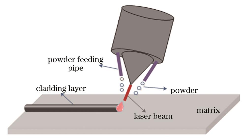
Fig. 2. Schematic of coaxial powder feeding laser cladding process
Fig. 3. Photo of thermal fatigue testing machine
Fig. 4. Shape and size of thermal fatigue specimen
Fig. 5. Crack propagation pattern on the surface of cladding layer and sampling diagram. (a)Crack propagation pattern; (b) sampling diagram
Fig. 6. Thermal fatigue crack length test. (a) Schematic of sample crack length test; (b) software statistics of crack length
Fig. 7. Thermal fatigue crack propagation of matrix material
Fig. 8. Crack morphologies in thermal fatigue process of matrix material. (a) 400 thermal cycles; (b) 500 thermal cycles; (c) 900 thermal cycles; (d) 1000 thermal cycles; (e) 1500 thermal cycles ; (f) 2000 thermal cycles
Fig. 9. Microstructure changes of matrix material after 2000 thermal cycles. (a) Original microstructure; (b) (c) microstructure and its partially enlarged view after 2000 thermal cycles
Fig. 10. Relationship between the number of thermal cycles and crack length for matrix and cladding samples
Fig. 11. Oxidation corrosion pit on the interface. (a) 80 thermal cycles; (b) 120 thermal cycles; (c) 160 thermal cycles
Fig. 12. Transverse crack at the interface. (a) 500 thermal cycles; (b) 1000 thermal cycles
Fig. 13. Crack passivation. (a) 1500 thermal cycles;(b) 2000 thermal cycles
Fig. 14. Effect of preheating temperature on thermal fatigue property of cladding layer
Fig. 15. Microstructures of cladding layer before heat treatment.(a) M7C3 hard phase at grain boundary; (b) M23C6 type intragranular carbide
Fig. 16. Position of energy spectrum analysis points of cladding layer before heat treatment
Fig. 17. Microstructures of cladding layer after heat treatment. (a) Zone 1; (b) zone 2
Fig. 18. Position of energy spectrum analysis points of cladding layer after heat treatment
Fig. 19. Macro morphologies of heat-treated cladding samples during 2000 thermal cycles. (a)(b) 500 thermal cycles; (c)(d) 1000 thermal cycles; (e)(f) 1500 thermal cycles; (g)(h) 2000 thermal cycles
Fig. 20. Morphologies of notch at the tip of heat-treated cladding sample after 2000 thermal cycles. (a) Whole view; (b) enlarged A zone; (c) enlarged B zone; (d) enlarged C zone
Fig. 21. Microstructures of heat-treated cladding sample before and after 2000 thermal cycles. (a) Before thermal cycles; (b) after 2000 thermal cycles
| |||||||||||||||||||||||||||||||||||||||
Table 1. Chemical composition of matrix material and iron-based powder
| |||||||||||||||||||||||
Table 2. Mass fraction of elements in cladding layer before heat treatment
| |||||||||||||||||||||||
Table 3. Mass fraction of elements in cladding layer after heat treatment

Set citation alerts for the article
Please enter your email address
© Copyright 2018-2021 | Chinese Laser Press. All Rights Reserved 沪ICP备15018463号-20