Antichiral gyromagnetic photonic crystal (GPC) in a honeycomb lattice with the two interpenetrating triangular sublattices A and B magnetically biased in opposite directions can realize antichiral one-way edge states propagating along the same direction at its two parallel edges. Here, we report the construction and observation of topological beam splitting with the easily adjustable right-to-left ratio in an antichiral GPC. The splitter is compact and configurable, has high transmission efficiency, and allows for multi-channel utilization, crosstalk-proof, and robust against defects and obstacles. This magnificent performance is attributed to the peculiar property that antichiral one-way edge states exist only at zigzag edge but not at armchair edge of antichiral GPC. When we combine two rectangular antichiral GPCs holding left- and right-propagating antichiral one-way edge states respectively, bidirectionally radiating one-way edge states at two parallel zigzag edges can be achieved. Our observations can enrich the understanding of fundamental physics and expand topological photonic applications.
Introduction
Topological insulators1, whose bulky states are prohibited while surface/edge states are conductive and topologically protected, attract an abundance of research in many different fields, including photonics2-6, acoustics7-10, mechanical waves11, electronic circuits12 , and matter waves13, etc. Especially, recent advances in topologically protected edge states have drawn growing attention in the optics and photonics community14-28, which have been found and confirmed in various photonic systems, e.g. gyromagnetic14-17, metamaterial18, 19, Floquet20, 21, nonlinear22, 23, liquid-crystal24, non-Hermitian25, non-Abelian26 , and synthetic dimension27, 28. They also have inspired the discovery of intriguing transport phenomena and helped to achieve novel applications, e.g. topological laser29-33, topological fibre34, topological quantum circuit35 , and topological delay line36-39.
A prominent means to create topologically protected edge state is a gyromagnetic photonic crystal (GPC) immersed in the external magnetic field thereby breaking the time-reversal symmetry14-17. In 2008, Raghu and Haldane first theoretically predicted that topologically protected one-way edge state can be created by analogy to the integer quantum Hall effect in two-dimensional electron gas system14. Consequently, some authors15-17 experimentally observed topologically protected one-way edge state in the square and honeycomb GPCs. In all these works, topologically protected one-way edge states display the chirality where the one-way edge states propagate along the opposite directions at two parallel edges of a bulk GPC, and they are called chiral one-way edge states.
Recently, we theoretically proposed another intriguing case where the one-way edge states at two opposite parallel zigzag edges can propagate in the same direction, and they are called antichiral one-way edge states40. These antichiral one-way edge states can be realized in a GPC with a honeycomb lattice consisting of two interpenetrating triangular sublattices A and B being immersed in opposite external magnetic fields respectively, and they are also robust against backscattering from defects, obstacles and sharp bends. Later on, Zhou et al. experimentally observed this antichiral one-way edge state in a similar GPC system41. To date, antichiral one-way edge states have been studied in various systems, such as exciton polariton strips42, graphene structures43, 44, Heisenberg ferromagnets45, acoustic resonators46, and recently have been realized in photonic crystals41 and electric circuits47. Very recently, Zhang et al. also theoretically realized reconfigurable light imaging in an antichiral gyromagnetic photonic crystal with both broken time-reversal and inversion symmetries48. Although there are many of studies focused on the demonstration of antichiral one-way transport property, little of them touch the unique properties of antichiral topological systems and novel applications.
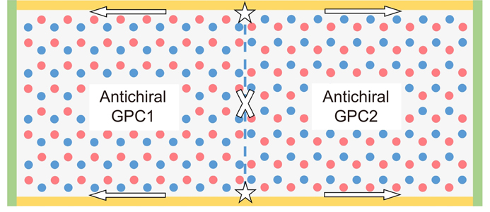
Here, we consider a rectangular bulk GPC of a honeycomb lattice with zigzag and armchair edges. When two interpenetrating triangular sublattices A and B are immersed in opposite external magnetic fields respectively, we observe that antichiral one-way edge states can only exist at zigzag edges and will not exist at armchair edges. Utilizing this unique feature, we combine two rectangular antichiral GPCs biased by opposite external magnetic fields, so that they can support left- and right-propagating antichiral one-way edge states respectively, to construct a compound antichiral GPC, as shown in Fig. 1. We demonstrate that bidirectionally radiating one-way edge states from the sources placed at the boundary of two GPC bulks can be achieved with high-efficiency, being reflection-free, crosstalk-proof, and robust against obstacle. Based on these unique features, we realize a topological beam splitter with configurable splitting ratio. Our results will enrich the understanding of fundamental physics underlying topological photonics and help design and construct novel topological photonic devices.
Figure 1.Schematic illustration of antichiral gyromagnetic photonic crystal. GPC1 and GPC2 are oppositely magnetized, and their interface is marked by a blue dotted line. The white stars and arrows are the sources and the transport directions of edge states, and white cross indicates that the waveguide does not support any transmission. Only TE polarization (where electric field is parallel to z direction) is considered.
We consider a two-dimensional rectangular GPC with a honeycomb lattice of yttrium-ion-garnet (YIG) gyromagnetic cylinders immersed in air, as seen in Fig. 2(a) and 3(a). The lattice constant along the x direction is a=10.0 mm, and the radius of YIG cylinders is r=1.5 mm. The rectangular GPC possesses two types of edge, where the zigzag edge is along x direction and the armchair edge is along y direction. There are five layers in the entire experimental configuration, with the top (1st) and bottom (5th) layers being the honeycomb array of NdFeB permanent magnet rods, the center (3rd) layer being the GPC structures made from honeycomb array of YIG rods, and the 2nd and fourth layers being the metal confinement layers. Two aluminum alloy plates with thickness h1=h5=2 mm are set in the first and fifth layers. A honeycomb array of holes are drilled into both plates, and a pair of N and S NdFeB permanent magnet rods are pressed tightly into these face-to-face holes in these two layers, so that the displacement of magnets owing to the attraction and repulsion of different magnets is completely avoided. Each NdFeB cylinder is of radius 2 mm and height 2 mm. These NdFeB cylinder pairs can apply one-to-one external magnetic field to the YIG cylinders. By flipping the biasing direction of magnets at neighboring sites, opposite magnetic fluxes are uniformly applied on the sublattices A and B in the x-y plane. The crystal of YIG cylinders (third layer with height h3=5 mm) is placed in an air-loaded planar waveguide sandwiched between two parallel aluminum alloy layers (i.e. second and fourth layers with height h2=h4=1 mm) that are used to completely forbid the EM waves from leaking off in the z direction. In this case, the polarization is identical to the pure TE states in two-dimensional photonic crystals. The transmission measurement is made with the Keysight P9374A vector network analyzer, which supports EM waves with frequency ranging from 300 kHz to 20 GHz.
Figure 2.Construction of antichiral gyromagnetic photonic crystal. (a) Schematic illustration of antichiral GPC. The antichiral GPC possesses the zigzag and armchair edges along the x and y directions respectively. (b) First Brillouin zone of honeycomb lattice. (c) Nonmagnetized GPC. The nonmagnetic gyromagnetic cylinders are marked as the gray circles. The frequencies of Dirac points at K and K' points are 8.85 GHz. (d) Uniformly magnetized GPC. All gyromagnetic cylinders are applied with external magnetic fields along +z (red) directions. The green region is the complete bandgap ranging from 9.10 to 9.40 GHz. (e) Compound magnetized GPC. Two sublattices A and B are applied with external magnetic fields along –z (blue) and +z (red) directions respectively. The frequency of Dirac points (red points) at K and K' points is 9.10 GHz and 9.40 GHz respectively.
The relative permittivity and permeability of the air are ε1=1 and μ1=1, respectively. The gyromagnetic material is yttrium iron garnet (YIG), a ferrite with measured relative permittivity 14.5 and dielectric loss tangent 0.0001. Its measured saturation magnetization is Ms=1950 Gauss, with a ferromagnetic resonance linewidth of 20 Oe. Typically, the magnetization will decrease to a negligible value without the presentence of the external magnetic field. The relative magnetic permeability of the YIG has the form
where
,
,
,
,
is the external magnetic field,
is the gyromagnetic ratio,
is the damping coefficient, and ω is the operating frequency. The band structure and all the simulations are calculated by using the commercial software COMSOL MULTIPHYSICS with RF module in frequency domain, and only E polarization (where the electric field E is parallel to the z-axis direction) is considered.
We first calculate and analyze the band structures of nonmagnetized, uniformly magnetized and compound magnetized GPC to discuss the construction of antichiral one-way edge state. Figure 2(b) shows the first Brillouin zone. As shown in Fig. 2(c), when all gyromagnetic cylinders are nonmagnetized, there is no bandgap between the first and second band, because these two bands intersect with each other at two Dirac points at points K and K' in the first Brillouin zone, and the band structure is symmetric about the high symmetry point M. The frequencies of two Dirac points are at 8.85 GHz and the slope of the green dotted line connecting two Dirac points is zero, so there are no one-way edge states. Besides, when all gyromagnetic cylinders are uniformly magnetized along the +z direction, as plotted in Fig. 2(d), the time-reversal symmetry of GPC is broken, the degeneracy of Dirac points at points K and K' are lifted up, and the band structure is still symmetric about the high symmetry point M. As a result, the first and second bands separate from each other, and then a complete bandgap with a pair of chiral one-way edge states emerges (green zone). The frequency range of this bandgap (marked as the green region) extends from 9.10 to 9.40 GHz, thus the bandgap width is 0.30 GHz. Moreover, when two sublattices A and B are magnetized along the –z and +z directions respectively, as illustrated in Fig. 2(e). The first and second bands are not separated from each other and still intersect at Dirac points at points K and K'. However, the band structure tilts and loses the symmetry about point M in the first Brillouin zone because the Dirac points at points K and K' move down and up respectively, resulting in the appearance of antichiral one-way edge states at the zigzag edges. Obviously, the slope of the green dotted line connecting two Dirac points is a positive value instead of being zero. The frequencies at points K and K' are 9.10 and 9.40 GHz respectively, and their difference is also 0.30 GHz, which is consistent with the bandgap width of Fig. 2(d).
We apply negative and positive magnetic fields to sublattices A and B respectively, which creates the sublattice symmetry breaking. Notably, the geometry used in obtaining the simulated and experimental data is a zigzag ribbon along the x direction, as shown in Fig. 3(a). Figure 3(b) shows that there exist two mutually intersecting dispersion curves degenerate with each other and possessing identical dispersion behavior around kx=1/2 (2π/a) and within 9.10~9.40 GHz. We plot the eigenmodal field profiles corresponding to the points 1, 2, 3 and 4 at 9.30 GHz in Fig. 3(c). There exist two edge states (eigenmodes 2 and 3) and two bulk states (eigenmodes 1 and 4). Because the slope for the edge states is positive while the slope for the bulk states is negative, the edge states and the bulk states will only propagate rightwards and leftwards respectively. Thus, these two one-way edge states propagate along the same direction at both zigzag edges, showing the antichirality. Besides, since these antichiral one-way edge states occur only in gapless system, they need the associated bulk states to transport in opposite direction to ensure the energy conservation40, 41.
Figure 3.Single antichiral gyromagnetic photonic crystal possessing zigzag and armchair edges.(a) Experimental setup. (b) Projected band structure along zigzag edge. (c) Eigenmodal field profiles in panel (b). (d) Calculated electric field distribution. (e) Unprocessed transmission data at zigzag edge in simulation. (f–g) Unprocessed transmission data measured at upper and lower zigzag edges respectively in experiment.
When we set two point sources (marked as stars) oscillating at 9.30 GHz at both zigzag edges [Fig. 3(d)], antichiral one-way edge states are excited. These two edge states at both zigzag edges transport rightwards with high-efficiency transmission, as shown in Fig. 3(e) by simulation. Since the upper and lower zigzag edges both support the right-propagating one-way edge states, their transmission data are completely coincident (i.e. S21=S43, S12=S34). The measured transmission data at the upper and lower zigzag edges are plotted in Fig. 3(f) and 3(g). They are not exactly the same, due to the inevitable departure in two measurements induced by uncontrollable subtle experimental details, but they remain strongly nonreciprocal between 9.10 and 9.40 GHz, with a 30–40-dB difference between the rightward and leftward transmissions. These experimental results agree well with the theoretical prediction in Fig. 3(e). It should be noted that the transmission in the experimental results is smaller than that in the numerical results, and the transmission loss mainly originates from the coupling loss at input/output end and the fabrication errors of the sample. This transmission property can be improved by using the transmission lines with lower loss, fabricating a closed waveguide cavity, and reducing the coupling loss at the input/output end.
Next, we calculate the projected band structure and eigenmodal field of antichiral GPC along armchair edge. Notably, the geometry used in obtaining the simulated and experimental data is an armchair ribbon along the y direction, as shown in Fig. 4(a). Figure 4(a) shows that there exists a bandgap within 9.255~9.335 GHz (yellow region). We choose four eigenmodes 1, 2, 3 and 4 at 9.14 and 9.41 GHz and plot their eigenmodal fields [Fig. 4(b)]. Their electric fields are dispersed uniformly in the bulk, meaning that there are no edge states localized at the armchair edge. Besides, the eigenmodal field distribution at same frequency are symmetrical, indicating that the transport of bulk states is reciprocal. We further place the perfect electric conductors adjacent to the lower zigzag and right armchair edges to form a zigzag-armchair waveguide channel [Fig. 4(c)]. We set a point source oscillating at 9.30 GHz at lower zigzag edge. EM wave can unidirectionally transport along the lower zigzag edge, but when it meets the lower right 90° corner, it cannot bypass the corner and couple to the right armchair edge. One can see that, although there exists some energy leaking to the left of the excitation source, they will eventually transport rightwards40. We proceed to place a point source oscillating at 9.30 GHz at the right armchair edge, and Fig. 4(d) shows that no edge state can be excited. These results indicate that the armchair edge does not support any edge states and thus the right armchair waveguide channel is closed. The simulated transmission spectra in Fig. 4(e) also show that there exists a bandgap within 9.255~9.335 GHz and there is no edge state at the armchair edge. Besides, the experimental results in Fig. 4(f) are also in full agreement with the theoretical results. The physics underlying this surprising distinctive feature is that when we apply opposite external magnetic fields to the two sublattices A and B respectively, the sublattice symmetry of GPC is broken. Then the Dirac points at K and K' valley will up-move and down-move respectively, resulting in the tilting of the band structure. As a result, the antichiral one-way edge states are only generated at two parallel zigzag edges and no antichiral one-way edge states are created at armchair edges. However, it should be emphasized that for a chiral GPC of honeycomb lattice, the time-reversal symmetry is broken when uniformly magnetized but the sublattice symmetry is still preserved, so the chiral one-way edge states can exist at both the zigzag and armchair edges49.
Figure 4.Band structure and transport behavior along armchair edge. (a) Projected band structure. (b) Eigenmodal field profiles in (a). (c) Electric field distribution of edge states propagating along zigzag-armchair waveguide. (d) Electric field distribution of edge states propagating along armchair waveguide. In simulations, the green and yellow boundaries are set as scattering boundary conditions and perfect electric conductors respectively. The excitation frequency is 9.30 GHz. (e) Unprocessed transmission data calculated at the right armchair edge in simulation. (f) Unprocessed transmission data measured at the right armchair edge in experiment.
We proceed to construct a compound antichiral GPC consisting of two rectangular GPCs biased by opposite external magnetic fields, and their interface is marked by a blue dotted line [see Fig. 5(a) for the practical experimental setup], and the other three combinations can be viewed in Supplementary information. We place two point sources oscillating at 9.30 GHz at the center of upper and lower zigzag edges to excite one-way edge states. As shown in Fig. 5(b), there exist two pairs of bidirectionally radiating one-way edge states at the upper and lower zigzag edges. Almost no EM wave passes through the middle channel composed of two armchair edges, meaning that the upper and lower edge states are independent and will not couple with each other, thus, these four one-way edge states are crosstalk-proof. The measurement results illustrated in Fig. 5(d–g) also show that the four waveguide channels all support one-way edge states, where the transmission in each channel is strongly nonreciprocal at 9.255~9.335 GHz.
Figure 5.Compound antichiral GPC supporting bidirectionally radiating one-way edge states. (a) A clear look at the fabricated sample with the first and second layers removed. (b–c) Simulation results of without and with metallic obstacles (yellow cylinders) respectively. The excitation frequency is 9.30 GHz. Unprocessed transmission data measured at four one-way waveguide channels (d–g) without and (h–k) with metallic obstacles.
We further replace four YIG cylinders at upper and lower edges with four metal cylinders [Fig. 5(c)]. The two pairs of bidirectionally radiating one-way edge states can bypass the metallic obstacles and propagate forwards almost perfectly. The experimental measurement results are plotted inFig. 5(h–k). Compared with Fig. 5(d–g), the transmission characteristics in the unperturbed and perturbed cases remain almost the same, although there exists some disturbance in the magnitude. The difference between forward and backward transmission is still large, e.g. about 35 dB in the vicinity of 9.30 GHz. We also provide the simulation result in Supplementary information that the bidirectionally radiating one-way edge states can bypass the rectangular metallic obstacle and continue forwards almost without any backscattering. Thence, the bidirectionally radiating one-way edge states at the two opposite parallel zigzag edges of a compound antichiral GPC have major advantages of high-efficiency, being reflection-free and crosstalk-proof, and robustness against obstacles. More importantly, we must note that such a high performance topological beam splitting is not possible to be realized in other better-studied PC systems, such as trivial PC50, topological valley- and spin-Hall photonic crystals51, 52, and chiral topological photonic crystal53, 54 (see Supplementary information for the beam splitting based on various physical mechanisms).
Configurable topological beam splitting
We proceed to design a topological beam splitting with the configurable splitting ratio easy to be adjusted by simply changing the source excitation condition. We consider EM waves incident from the lower zigzag edge as the excitation source. The incident angle φ is defined as the angle between the incident EM wave and the lower zigzag edge [Fig. 6(a–c)]. We calculate and show the electric field intensity pattern in right and left channels, draw the line scanning of calculated results along the lower zigzag edge, and directly superimpose these figures for the clarity to show clearly the energy ratio of left and right channels.
Figure 6.Variable-ratio topological beam splitting. (a–c) Electric field distributions in simulation. The excitation frequency is 9.30 GHz. (d–f) Unprocessed transmission data measured of S31 and S21 parameters. (g) Normalized transmission data of S31 and S21 parameters in (d-f).
When φ=30°, the one-way edge states of left and right channels both are excited, but the major energy flux is transmitted rightwards, and the energy ratio of them is about 1:5 [Fig. 6(a)]. When φ increases to 60°, more energy flux is transferred to the left channel, so that the energy ratio of them is about 3:5 [Fig. 6(b)]. When EM wave is incident perpendicular to zigzag edge (i.e. φ=90°), the energy flux is evenly split and transmitted to two channels [Fig. 6(c)]. When the incident angle continues to increase from 90° to 180°, the energy ratio of the left channel begins to dominate, e.g. when φ=120° and 150°, the energy ratios are about 5:3 and 5:1 respectively. The measured transmission data of lower channel (i.e. S21 and S31 parameters) at φ=30°, 60° , and 90° are shown in Fig. 6(d–f). We further normalize S21 and S31 parameters of Fig. 6(d–f), i.e. the sum of transmission parameters S21 and S31 is 1, and the results are plotted in Fig. 6(g). At 9.255~9.335 GHz, when φ increases from 30° to 90°, the transmission of the right channel decreases gradually, while that of the left channel increases. Thus, by continuously controlling the excitation angle of EM waves, the flow of EM waves at 9.255~9.335 GHz is split into the left and right directions, and the splitting ratio is configurable in an easy way. Similarly, the upper zigzag edge can also implement the configurable topological beam splitting functionality. As a result, the compound antichiral GPC can provide a powerful path to realize high-density dual-edge four-channel configurable topological beam splitting.
Conclusion and discussion
In summary, we have realized a compact dual-edge four-channel configurable topological beam splitting with the right-to-left splitting ratio adjustable. It is attributed to the peculiar property that antichiral one-way edge states exist only at zigzag edge but not at armchair edge. This scheme solves a challenging task for the realization of topological beam splitting, which is more compact and configurable, has high transmission efficiency, allows for multi-channel utilization, crosstalk-proof, and robust against defects and obstacles induced from manufacturing. Our experimental results show that the difference between forward and backward transmission is about 30~40-dB, and this strong nonreciprocity can well satisfy practical needs.
Our results are of significance not only in the basic understanding of fundamental physics underlying topological photonics, but also in offering useful insights and routines to design novel topological photonic devices which can be used to build nonreciprocal microwave devices such as configurable topological beam splitter, compact multi-channel one-way waveguides40, reflection-free one-way waveguides with sharp corners41 and even reconfigurable light imaging48. Besides, the magnetic field exerted on the GPC comes from tiny permanent magnets, which avoids the use of large magnetic field equipment. So they do not add volume to the microwave devices, and would not be an issue in constructing practical microwave topological devices. Finally, we can construct nonreciprocal microwave device with a more compact setup in a more economical and flexible way.
Moreover, although our work has focused on GPC, similar ideas can be more broadly generalized to not only the other systems in photonics, e.g. Floquet20, 21, liquid-crystal24, and synthetic dimension27, 28 topological insulators, but also in other physical fields, e.g. exciton polariton strips42, graphene structures43, 44, Heisenberg ferromagnets45, acoustic resonators46 , and electrical circuits47.
We are grateful for the financial support from the National Natural Science Foundation of China (11974119), Science and Technology Project of Guangdong (2020B010190001), Guangdong Innovative and Entrepreneurial Research Team Program (2016ZT06C594), and National Key R&D Program of China (2018YFA 0306200).
All authors contributed extensively to this work. J. Chen performed the simulation and carried out the experiments. J. Chen and Z. Y. Li raised the idea, provided major theoretical and experimental analysis, and wrote the manuscript. Z. Y. Li supervised the project. All authors participated in discussions and reviewed the manuscript.
The authors declare no competing financial interests.