
Xu Liu, Chaoyong Tan, Yong Cheng, Jingsong Wei, Mengzhen Zhu, Xia Chen, Chaowei Mi. 7 kHz sub-nanosecond microchip laser amplified by a grazing incidence double pass slab amplifier[J]. Chinese Optics Letters, 2021, 19(2): 021403
- Chinese Optics Letters
- Vol. 19, Issue 2, 021403 (2021)
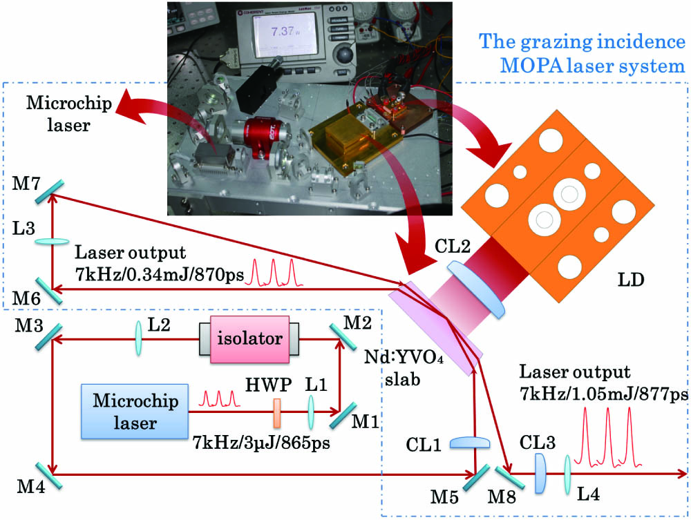
Fig. 1. Setup of the grazing incidence MOPA laser system.
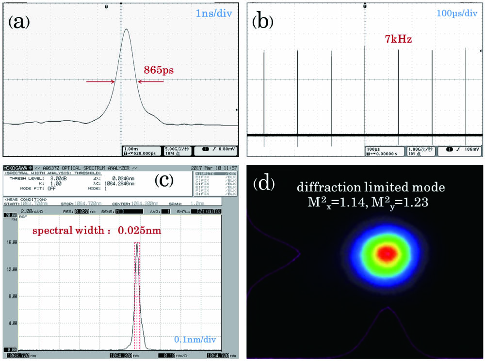
Fig. 2. Output of the master oscillator. (a) The pulse duration, (b) the pulse repetition rate, (c) the output spectrum, and (d) the output beam profile.
Fig. 3. Schematic diagram of
Fig. 4. Design of the grazing incidence of
Fig. 5. Output power versus pump power for the single pass and double pass amplification.
Fig. 6. Extraction efficiency
Fig. 7. Output spectrum of the double pass amplification. (a) The output spectrum with 41 W pump power and (b) the output spectrum with 55 W pump power.
Fig. 8. Waveform of 7.37 W output for the double pass amplifier. (a) The pulse duration and (b) the pulse repetition rate.
Fig. 9. Output beam profile of the double pass amplifier.

Set citation alerts for the article
Please enter your email address
© Copyright 2018-2021 | Chinese Laser Press. All Rights Reserved 沪ICP备15018463号-20