
Xu Liu, Chaoyong Tan, Yong Cheng, Jingsong Wei, Mengzhen Zhu, Xia Chen, Chaowei Mi. 7 kHz sub-nanosecond microchip laser amplified by a grazing incidence double pass slab amplifier[J]. Chinese Optics Letters, 2021, 19(2): 021403
- Chinese Optics Letters
- Vol. 19, Issue 2, 021403 (2021)
Abstract
1. Introduction
Many ladar systems and scientific applications such as space-flight laser altimetry for earth science require sub-nanosecond short pulse width and high peak power laser pulses[
For the wide absorption and large emission cross sections and proper fluorescence lifetime of crystals, many diode-pumped MOPA systems were reported[
In this Letter, we demonstrate a 7 kHz sub-nanosecond microchip laser amplified by a grazing incidence double pass slab amplifier. The configuration can shorten the pulse width and spectral line width by the microchip laser and enhance peak power by the bounce amplifier. The grazing angle of the amplifier has been chosen carefully, where the mode size of the injected seed and the amplifier gain sheet dimensions are well matched. The laser system generates 25 pm spectral line width, 1.05 mJ pulse energy, and 877 ps pulse duration at 7 kHz repetition rate with dimensions of . The output power instability reaches , while the laser has operated continuously for 30 min.
Sign up for Chinese Optics Letters TOC. Get the latest issue of Chinese Optics Letters delivered right to you!Sign up now
2. Experiments
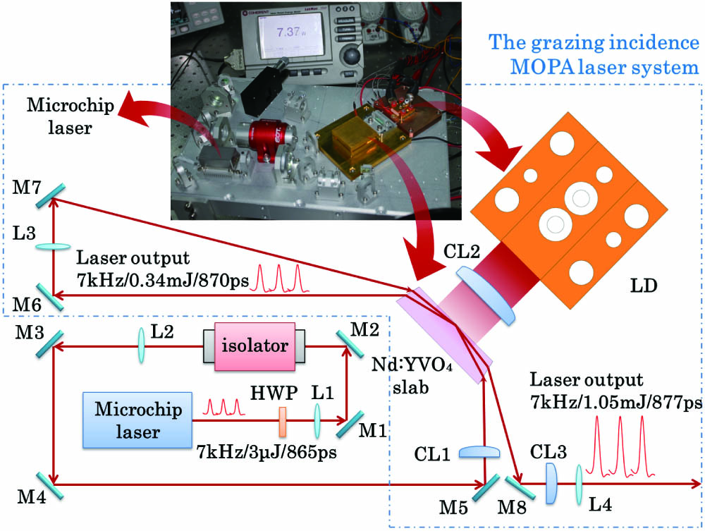
The schematic diagram for the sub-nanosecond microchip laser and grazing incidence double pass slab amplifier system is shown in Fig. 1. Owing to the good overlap between and gain bandwidths, we can exploit both materials’ favorable characteristics, taking advantage of physical properties for an efficient passively Q-switched oscillator, and design a simple, compact, grazing incidence amplifier configuration.
![]()
Figure 1.Setup of the grazing incidence MOPA laser system.
The master oscillator is a passively Q-switched microchip laser, longitudinally end-pumped by a pulse-driven diode laser, using a pump modulation technique, which can obtain much smaller energy jitter. The microchip is mounted in a thermally controlled holder. By a proper choice of unsaturated transmission and output coupling, the microchip laser is properly set to achieve 3 µJ, 865 ps pulses [Fig. 2(a)] at 7 kHz repetition rate [Fig. 2(b)] (average power 21 mW). The central wavelength is found to locate at 1064.28 nm, and the spectral width is 0.025 nm [Fig. 2(c)]. Diffraction limited mode operation is observed at the repetition rate of 7 kHz. The beam ellipticity is measured to be 0.94, and the beam quality is and [Fig. 2(d)].
![]()
Figure 2.Output of the master oscillator. (a) The pulse duration, (b) the pulse repetition rate, (c) the output spectrum, and (d) the output beam profile.
As the fluorescence lifetime of is only about 100 µs, compatible with the injected seed signal, the amplifier’s pump diode is set to operate at 7 kHz, and each pump pulse duration is 100 µs. In order to optimize the energy extraction in the slab amplifier, it is also worth noticing that the polarization of the seed and pump beam should be well matched for the slab. As the gain property of crystal is polarization relevant, the polarization of the conduction cooled packaged LD is set parallel to the c axis of the slab, and a half-wave plate (HWP) is used to control the polarization direction of the seed laser, as shown in Fig. 1.
The a-cut crystal is a , 13° wedged slab. The Nd-doping level is 1% (atomic). The input and output faces of the slab are antireflection (AR) coated at 1064 nm, and the pumped face is AR coated at 808 nm. The two faces of the slab are welded to copper heat sink by indium, as shown in Fig. 3(b). The waste heat is transferred by a thermoelectric cooler (TEC). The slab is pumped by a TE polarized CS packaged LD; the maximum pump power is 55 W at 808 nm (25°C). The pump beam is collimated by a cylindrical lens (CL2, shown in Fig. 1), yielding a vertical laser gain sheet of about 200 µm and horizontal gain area of about 10 mm [shown in Figs. 3(c) and 3(d)]. The polarization of the pump light is parallel to the c axis of the slab. The LD is mounted on a copper heat sink. A TEC is used to control the temperature of the LD. All of the components of the grazing incidence MOPA laser labeled in Fig. 1 are packaged in a volume of . The laser engineering prototype is air-cooled. Both the slab and the LD are set to operate at 25°C.
![]()
Figure 3.Schematic diagram of
![]()
Figure 4.Design of the grazing incidence of
The optimization of the energy extraction efficiency and the control of the thermal aberrations are achieved by carefully matching the mode size of the injected seed to the amplifier gain sheet dimensions. For that reason, the transverse seed spot needs a different focusing along the vertical and horizontal axes, and the seed beam is reshaped by a CL and then injected into the amplifier. In order to maximize the gain while avoiding clipping effects, the grazing angle has been chosen to be 10° for first pass and 6° for double pass, as shown in Fig. 4(c). For the double pass grazing angle to be 6°, the beam width of 1 mm becomes 1.33 mm on horizontal axis and less than 200 µm on vertical axis inside the amplifier medium, which can obtain a 12.7 mm bounce width and 0.67 mm bounce depth [Fig. 4(b)]. The gain sheet dimensions [Figs. 3(c) and 3(d)] and the pump depth are well matched.
The Faraday magnetic-optic isolator shown in Fig. 1 is necessary for MOPA operation. In the double pass sketch, the backward propagating spontaneous emission originating at the output end of the amplifier may pass through the amplifier twice and be amplified. Then, at the output mirror of the master oscillator, parts of the amplified spontaneous emission (ASE) will reflect back into the amplifier and be quickly amplified along the single pass and double pass beam path because of its extremely high gain; thus, the effective energy extraction efficiency will be decreased. At the same time, the transmitted ASE at the output mirror will feed back into the microchip laser. This effect might increase the number of modes lasing in the microchip and significantly change the master oscillator’s spectrum.
The output power curve versus the pump power is shown in Fig. 5. With 41 W diode pump power, a maximum of 2.4 W amplified output power at the pulse repetition rate of 7 kHz is achieved under single pass amplification, and 7.37 W amplified output power is achieved under double pass amplification. The output power extraction efficiency (optical-to-optical efficiency) is 18%; it is a higher extraction efficiency for the sub-nanosecond laser amplifier[
![]()
Figure 5.Output power versus pump power for the single pass and double pass amplification.
Theoretically, the energy of a small-signal light will be increased when passing through the amplifier, and the output fluence can be expressed as[
The extraction efficiency is an indicator of the energy release of an amplifier. During the first pass of a small signal, can be written as
The gain for the second pass is lower, and the gain coefficient in the expression should be replaced by
With parameters of the slab amplifier used in experiments, a numerical simulation is finished to demonstrate the extreme of amplification. The extraction efficiency curves of single pass and double pass are shown in Fig. 6. The experimental extraction efficiency of the two, calculated from the maximal output power in Fig. 5, is pointed out in Fig. 6 as well. Due to the decreasing grazing angle of the double pass, the second one better matches the amplifier gain sheet dimensions and achieves a greater extraction efficiency, which is close to the simulated result.
![]()
Figure 6.Extraction efficiency
The spectrum of the double pass amplifier is shown in Fig. 7(a). As the unwanted ASE is suppressed, the spectrum of the double pass amplifier is almost the same as that of the master oscillator, and the spectral width is 0.025 nm too. When increasing the pump power to larger than 41 W, the ASE grows quickly to an unacceptable level. When the pump power increases to 55 W, the ASE power is even larger than the signal power, as shown in Fig. 7(b), and the measured laser emission spectrum consists of two modes spaced 0.22 nm apart. The signal is still located at 1064.28 nm, but the ASE emission is located at 1064.06 nm. For this, the pump power should be limited to not larger than 41 W. The output power instability is measured to be less than , while the laser has operated continuously for 30 min.
![]()
Figure 7.Output spectrum of the double pass amplification. (a) The output spectrum with 41 W pump power and (b) the output spectrum with 55 W pump power.
Temporal pulse shapes are observed in Fig. 8. Pulse duration of the double pass laser is about 877 ps [Fig. 8(a)] at 7 kHz [Fig. 8(b)] when the output power is 7.37 W. The amplified pulse width is found to be nearly the same and becomes slightly wider compared with that of the oscillator. A CL and a spherical lens are used to reshape the amplified beam into a circular symmetrical Gaussian beam. We focus the output beam to a beam waist and measure the diameter of the spot around the waist. The reshaped beam is shown in Fig. 9. The beam ellipticity is measured to be 0.89, less than that of the master oscillator. The double pass beam quality is measured to be and .
![]()
Figure 8.Waveform of 7.37 W output for the double pass amplifier. (a) The pulse duration and (b) the pulse repetition rate.
![]()
Figure 9.Output beam profile of the double pass amplifier.
3. Conclusions
In conclusion, a 7 kHz sub-nanosecond microchip laser amplified by a grazing incidence double pass slab amplifier is demonstrated. With 41 W diode pump power, laser output power of 7.37 W, 877 ps pulse duration, 25 pm spectral width, and near diffraction limited mode beam quality are achieved. The laser may be used for applications such as laser altimeters and ladar systems.
References
[1] A. W. Yu, M. A. Krainak, D. J. Harding, J. B. Abshire, X. Sun, L. Ramos-Izquierdo, J. Cavanaugh, S. Valett, T. Winkert, M. Plants, C. Kirchner, B. Kamamia, R. Faulkner, P. Dogoda, W. Hasselbrack, T. Filemyr. A 16-beam non-scanning swath mapping laser altimeter instrument. Proc. SPIE, 8599, 85990P(2013).
[16] Z. Sun, Q. Li, Y. Hui, M. Jiang, H. Lei. Compact diode-pumped nanosecond Nd:YVO4 grazing-incidence slab amplifier. Proc. SPIE, 9449, 94491G(2015).
[20] W. Koechner. Solid-State Laser Engineering(2006).

Set citation alerts for the article
Please enter your email address
© Copyright 2018-2021 | Chinese Laser Press. All Rights Reserved 沪ICP备15018463号-20