
Yi-Chen Liu, Dong-Jie Guo, Ran Yang, Chang-Wei Sun, Jia-Chen Duan, Yan-Xiao Gong, Zhenda Xie, Shi-Ning Zhu, "Narrowband photonic quantum entanglement with counterpropagating domain engineering," Photonics Res. 9, 1998 (2021)
- Photonics Research
- Vol. 9, Issue 10, 1998 (2021)
Abstract
1. INTRODUCTION
Quantum entanglement is the basis of fundamental quantum mechanics studies and quantum information technologies [1–3]. So far, the most developed entangled sources are via the optical approach because of its low decoherence and high purity. However, the entangled photon source needs to be compatible with information-processing devices for practical applications, where the photon–electron interaction is normally required. One important example is the memory [4–6] for quantum information, which is not only essential for quantum computation [7,8], but also necessary to realize quantum repeaters for long-distance quantum communication [9–12]. It is the ultimate solution to overcome the inevitable photon loss over large communication distances and regain the channel security and data rate. In the above cases, the bandwidth of such photon–electron interaction is fundamentally limited by the energy level of the electrons. The recent breakthrough in the solid-state quantum memories has pushed this bandwidth limit to the order of gigahertz [13–18], though such bandwidth is still too narrow for the conventional entangled photon sources based on spontaneous parametric downconversion (SPDC) [19,20]. Much effort has been devoted to shrinking the biphoton bandwidth, such as passive filtering [21,22] or cavity enhancement [23]. But it either reduces the brightness, or adds complexity and instability of the system. On the other hand, the counterpropagating phase-matching [24] geometry can inherently reduce the phase-matching bandwidth [25–28] without cavity interactions. This geometry relies on the optical microstructure manufacture, and such counterpropagating domain engineering has been demonstrated for mirrorless optical parametric oscillation [29] and SPDC [30–33].
Here we report the first narrowband photonic polarization entanglement generation using counterpropagating domain engineering. The state-of-the-art manufacture of 1.3 μm poling period in a Type II periodically poled potassium titanyl phosphate (PPKTP) waveguide enables 7.1 GHz biphoton bandwidth at telecom wavelength, as well as the deterministic separation of the counterpropagating signal and idler photons even at wavelength degeneracy. The bandwidth is directly measured in the spectral domain with scanning narrow-line filters, and also confirmed with the Hong–Ou–Mandel (HOM) interference [34]. Its high visibility of
2. EXPERIMENTAL SETUP
In experiment, the PPKTP waveguide is designed for Type II quasi-phase matching (QPM) backward spontaneous parametric downconversion (BSPDC). The waveguide was fabricated by ion implantation in ADVR Inc., with a length of 10 mm. To avoid spurious back reflections from the waveguide end faces, the sample is angle-polished at 10°. The poling length is also 10 mm, and the period is designed to be 1.3 μm. The measured coupling efficiency into/out of the waveguide is about 20% and 50% for laser light at 780 and 1550 nm, respectively. As illustrated in Fig. 1(a), a forward pump photon can generate a forward signal photon and a backward idler photon with polarizations along the
Sign up for Photonics Research TOC. Get the latest issue of Photonics Research delivered right to you!Sign up now
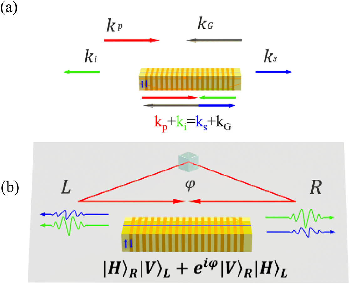
Figure 1.Scheme of the counterpropagating polarization-entangled photon source. (a) Phase-matching diagram of the BSPDC; (b) polarization entanglement generation from the BSPDC with bidirectional pump light.
Our experiment setup is shown in Fig. 2. The pump light is from a continuous-wave Ti:sapphire laser (SolsTis) and transmits in a triangle loop with the polarization beam splitter (PBS0). The power ratio between the R and L is controlled by rotating the optical axis angle of a half-wave plate (HWP0), and the relative phase can be finely tuned by the optical axis angle of HWP3 sandwiched between two 45° quarter-wave plates (QWP3 and QWP4). HWP4 is oriented as 45° to rotate pump polarization to H for SPDC. Then the two pump light beams are reflected by two dichroic mirrors (DMs) and coupled into the PPKTP waveguide in two opposite directions. The above state preparation setup is integrated on a solid metal housing, where the temperature is finely controlled by Peltier elements within accuracy of milli-Kelvin level. Therefore, the phase difference in the pump loop can be stabilized. The DMs are designed for high transmission for BSPDC outputs at telecom wavelengths, for direct output at R and L ports. The output photon pairs are then detected by two superconducting nanowire single-photon detectors (SNSPDs) with efficiencies over 90% at 1550 nm. Filter sets are used in the R and L ports for spectral cleaning, including a long-pass filter (Thorlabs FEL0900), a bandpass filter (Semrock NIR01-1570/3-25), and a homemade Fabry–Perot filter (FPF) (for details, see Appendix A) in each set.
![]()
Figure 2.Experimental setup. HWP, half-wave plate; QWP, quarter-wave plate; PBS, polarization beam splitter; DM, dichroic mirror; PC, polarization controller; LPF, long-pass filter; BPF, bandpass filter; FPF, Fabry–Perot filter; P, prism; SNSPD, superconducting nanowire single-photon detector; C.C., coincidence counts.
3. RESULTS
We first check the phase matching of the PPKTP waveguide by the backward second-harmonic generation (SHG) process. A tunable semiconductor laser (Santec TSL-710) with a linewidth of 100 kHz is used as the fundamental light (FL). It is first split into two beams and coupled into the waveguide through the R and L BSPDC output ports, which are set to V and H polarizations, respectively, so that the SHG light is phase-matched for the right propagation. By varying the laser wavelength, we record the SHG output power with a power meter (Thorlabs S154C) as a function of fundamental wavelength. As shown in Fig. 3, when the fundamental wavelength was tuned to 1553.48 nm, a maximum SHG output power of 99.5 nW was obtained. The main peak agrees well with the theoretical simulation from the function
![]()
Figure 3.SHG measurement. SHG output power as a function of FL wavelength. The red curve is a
For simplicity, we focus on the BSPDC pumped in a single direction by setting HWP0 to 0°. The BSPDC spectrum characterization is performed by scanning a homemade Fabry–Perot cavity (FPC) with a FWHM linewidth of 7.8 pm (for details, see Appendix A). This FPC transmission is much narrower than the bandwidth of BSPDC, where the transmitted signal or idler frequency can be tuned by varying its temperature. The BSPDC spectrum is achieved in a coincidence measurement for the best signal-to-noise ratio during the FPC scan. The measured signal and idler photon spectra are shown in Fig. 4(a), with identical bandwidth fitted to be 57 pm (7.1 GHz). Their central wavelengths can be finely tuned to match each other by varying the PPKTP waveguide temperature. The satellite peaks are higher than the expectations and nonsymmetric, which is due to fabrication imperfections of the waveguide. To clean the nonideal satellite peaks, we insert a pair of 100 μm thick FPFs (for details, see Appendix A). As shown in the Fig. 4(a) inset, the FWHM linewidth of each FPF is measured to be about 132 pm, which is larger than the 57 pm BSPDC bandwidth, and thus does not affect the central spectrum of the source.
![]()
Figure 4.BSPDC measurements. (a) Measurement of BSPDC spectrum. Black and red dots correspond to signal and idler photon spectra, respectively. The curve is fitted to
The quantum feature of a two-photon source can be presented by a high-visibility quantum interference. Here it is tested using the HOM interferometer, and the narrow bandwidth of the BSPDC spectrum can be also characterized from the correlation time in the interference measurement. Keeping the single-direction-pumped setup, we set the polarizations of the L and R output ports to make photons be reflected at PBS1 and PBS2, so that the BSPDC light is directed to a 50:50 fiber coupler for the HOM interference. A fiber polarization controller (PC3) is used to make the polarization of the two arms identical. The relative delay
The spectrum and HOM interference measurements directly show that we do produce photon pairs with narrow bandwidth in the BSPDC process. Then we can produce the polarization entanglement by rotating HWP0 away from 0°, and here we fix it at 45° for maximum entanglement generation, and adjust HWP3 to generate the singlet state
We first characterize the entanglement via polarization correlation measurement, where HWP2 is set to 0°, 45°, and
![]()
Figure 5.Entanglement correlation measurement. Coincidence counts are recorded as a function of HWP1 angle for changing the linear polarization projection measurement on one photon with the other photon projected to four states:
We further characterize the entanglement state using the standard quantum state tomography [36]. By inserting QWP1 and QWP2 in the L and R outputs, we can perform projection measurements on the four states
![]()
Figure 6.(a) Real and (b) imaginary parts of the reconstructed density matrix for the produced polarization entanglement state.
Our photonic polarization-entangled source relies on the superposition of two bidirectional BSPDC processes. As shown in Fig. 1(b), the superposition phase stability depends on the optical length difference between two pump arms from PBS0 to the PPKTP waveguide, which needs to be stabilized to subwavelength level. It is achieved by the balanced design in the two arms, and the whole source sits on a monolithic aluminum housing for temperature equilibrium. This design greatly cancels the phase sensitivity of the temperature change. For further stabilization, our source is built with the temperature stabilized by a Peltier cooler and sealed in a metal box. By using high-performance temperature controllers, the entangled source can be stabilized to milli-Kelvin level.
To test the phase stability, we project the entangled photons on the
![]()
Figure 7.Phase stability test. Coincidence counts for
4. CONCLUSION AND DISCUSSION
We have demonstrated the first narrowband photonic quantum entanglement generation by the state-of-the-art backward domain engineering in a PPKTP waveguide. The BSPDC geometry enables an inherent bandwidth of 7.1 GHz as well as deterministic separation of collinear frequency-degenerate polarization-entangled photon pairs. A phase-stabilized bidirectional pump can be easily achieved in balanced arm loop with only temperature control. We show an example of singlet state generation with a fidelity of
List of Narrowband Polarization-Entangled Photon Sources
| Polarization-Entangled | Method | Wavelength | Bandwidth | Brightness | Fidelity |
|---|---|---|---|---|---|
| Fedrizzi | Sagnac interferometer | 810 | 137 GHz | 0.597 | 99.78% |
| Kuzucu | Sagnac interferometer | 780.7 | 73.8 GHz | 4.22 | 98.85% |
| Sansoni | Two periodically poled waveguides | 1554 | 260 GHz | 38.7 | 97.3% |
| Herrmann | Biperiodic poling waveguide | 1551/1571 | 85 GHz | 7 | 97.5% |
| Sun | Dual-periodic poling waveguide | 1489.9/1335 | 270 GHz | 42 | 94.5% |
| Bao | Cavity and postselection | 780 | 9.6 MHz | 6 | 94% |
| Tian | Cavity and postselection | 795 | 15 MHz | 3 | 95.2% |
| This work | Counter propagating | 1553.5 | 7.1 GHz | 3.4 | 95.7% |
The counterpropagating domain engineering can also be adopted into the fast-developing lithium liobate thin-film platform, and the tight mode confinement can further boost the conversion efficiency in a much smaller footprint for large-scale integration. Therefore, it is a unique and powerful tool for narrowband photonic quantum entanglement generation, which links the photonic qubits to other key elements in the quantum information processing that requires photon–electron interaction, including quantum memory, which is important for quantum information technologies.
Acknowledgment
Acknowledgment. ZDX, YXG, and YCL conceived and designed the experiment. YCL, DJG, RY, CWS, and JCD performed the experimental measurements. SNZ, ZDX, and YXG supervised the project. YCL and DJG wrote the paper, with contributions from all authors.
APPENDIX A: FABRY–PEROT RESONATORS FOR BSPDC SPECTRUM MEASUREMENT AND CLEANING
We develop two types of Fabry–Perot resonators for the BSPDC spectrum measurement and cleaning, which are called the FPC and the FPF, respectively. Both resonators are double-sided coated plate (etalon) made of lithium niobate and polished to the thickness as required. The FPC has a linewidth much smaller than the BSPDC bandwidth, so that it can scan across the BSPDC spectrum, while the FPF linewidth is designed larger than the BSPDC bandwidth so that BSPDC spectral feature does not change after cleaning. The free spectral range (FSR) of the FPF is designed larger than the bandpass filter linewidth for best noise reduction.
High finesse is required for both resonators to achieve a high rejection ratio. From the coating design, the FPC and FPF have target finesses of 155.5 and 50.8, respectively. High-quality mechanical polishing and coating techniques are required to achieve that. As shown in Fig.
![]()
Figure 8.Characterization of the two Fabry–Perot resonators. (a) AFM image of FPC before and after coating; (b) Fabry–Perot resonator test setup. TSL, tunable semiconductor laser; PC, polarization controller; TC, temperature controller; FPC, Fabry–Perot cavity; FBS, fiber beam splitter; PD, photodetector. (c) FPC transmission intensity as a function of wavelength detuning from the center transmission peak. The upper inset shows the zoom-in of one transmission peak of 7.8 pm linewidth, and the lower inset is the measured temperature-wavelength relationship. (d) Transmission measurements for the FPF, with 6.17 nm FSR and 132 pm linewidth for the transmission peak.
Characterization of the FPC and FPF.
| Sample | Cavity Length (μm) | Reflectivity | Theoretical Linewidth (GHz) | Theoretical Finesse | Experimental Finesse | Cutoff (dB) |
|---|---|---|---|---|---|---|
| FPC | 400 | 98% | 1.1 | 155.5 | 125.6 | 30 |
| FPF | 100 | 94% | 13.1 | 50.8 | 46.7 | 30 |
We use a wavelength-tunable cw laser (Santec TSL-710) with a narrow linewidth of 100 kHz to scan the resonances, with absolute wavelength calibration using a wavelength meter (HighFinesse WS-6), as shown in Fig.
References
[1] J. L. O’Brien, A. Furusawa, J. Vuckovic. Photonic quantum technologies. Nat. Photonics, 3, 687-695(2009).
[2] J. I. Cirac, A. K. Ekert, S. F. Huelga, C. Macchiavello. Distributed quantum computation over noisy channels. Phys. Rev. A, 59, 4249-4254(1999).
[3] N. Gisin, G. G. Ribordy, W. Tittel, H. Zbinden. Quantum cryptography. Rev. Mod. Phys., 74, 145-195(2002).
[4] A. I. Lvovsky, B. C. Sanders, W. Tittel. Optical quantum memory. Nat. Photonics, 3, 706-714(2009).
[5] X.-M. Jin, J.-G. Ren, B. Yang, Z.-H. Yi, F. Zhou, X.-F. Xu, S.-K. Wang, D. Yang, Y.-F. Hu, S. Jiang, T. Yang, H. Yin, K. Chen, C.-Z. Peng, J.-W. Pan. Experimental free-space quantum teleportation. Nat. Photonics, 4, 376-381(2010).
[6] N. Gisin, R. Thew. Quantum communication. Nat. Photonics, 1, 165-171(2007).
[7] E. Knill, R. Laflamme, G. J. Milburn. A scheme for efficient quantum computation with linear optics. Nature, 409, 46-52(2001).
[8] P. Kok, W. J. Munro, K. Nemoto, T. C. Ralph, J. P. Dowling, G. J. Milburn. Linear optical quantum computing with photonic qubits. Rev. Mod. Phys., 79, 135-174(2007).
[9] L.-M. Duan, M. D. Lukin, J. I. Cirac, P. Zoller. Long-distance quantum communication with atomic ensembles and linear optics. Nature, 414, 413-418(2001).
[10] H. J. Briegel, W. Dur, J. I. Cirac, P. Zoller. Quantum repeaters: the role of imperfect local operations in quantum communication. Phys. Rev. Lett., 81, 5932-5935(1998).
[11] C. Jones, D. Kim, M. T. Rakher, P. G. Kwiat, T. D. Ladd. Design and analysis of communication protocols for quantum repeater networks. New J. Phys., 18, 083015(2016).
[12] H. J. Kimble. The quantum internet. Nature, 453, 1023-1030(2008).
[13] E. Saglamyurek, J. Jin, V. B. Verma, M. D. Shaw, F. Marsili, S. W. Nam, D. Oblak, W. Tittel. Quantum storage of entangled telecom-wavelength photons in an erbium-doped optical fibre. Nat. Photonics, 9, 83-87(2015).
[14] J. Jin, E. Saglamyurek, M. L. Puigibert, V. Verma, F. Marsili, S. W. Nam, D. Oblak, W. Tittel. Telecom-wavelength atomic quantum memory in optical fiber for heralded polarization qubits. Phys. Rev. Lett., 115, 140501(2015).
[15] E. Saglamyurek, N. Sinclair, J. Jin, J. A. Slater, D. Oblak, F. Bussieres, M. George, R. Ricken, W. Sohler, W. Tittel. Broadband waveguide quantum memory for entangled photons. Nature, 469, 512-515(2011).
[16] M. F. Askarani, M. L. G. Puigibert, T. Lutz, V. B. Verma, M. D. Shaw, S. W. Nam, N. Sinclair, D. Oblak, W. Tittel. Storage and reemission of heralded telecommunication-wavelength photons using a crystal waveguide. Phys. Rev. Appl., 11, 054056(2019).
[17] M. Rančić, M. P. Hedges, R. L. Ahlefeldt, M. J. Sellars. Coherence time of over a second in a telecom-compatible quantum memory storage material. Nat. Phys., 14, 50-54(2017).
[18] M. P. Hedges, J. J. Longdell, Y. Li, M. J. Sellars. Efficient quantum memory for light. Nature, 465, 1052-1056(2010).
[19] C. Kurtsiefer, M. Oberparleiter, H. Weinfurter. High-efficiency entangled photon pair collection in type-II parametric fluorescence. Phys. Rev. A, 64, 023802(2001).
[20] S. Tanzilli, H. D. Riedmatten, W. Tittel, H. Zbinden, P. Baldi, M. D. Micheli, D. B. Ostrowsky, N. Gisin. Highly efficient photon-pair source using periodically poled lithium niobate waveguide. Electron. Lett., 37, 26-28(2001).
[21] M. Halder, A. Beveratos, N. Gisin, V. Scarani, C. Simon, H. Zbinden. Entangling independent photons by time measurement. Nat. Phys., 3, 692-695(2007).
[22] M. Halder, S. Tanzilli, H. D. Riedmatten, A. Beveratos, H. Zbinden, N. Gisin. Photon-bunching measurement after two 25-km-long optical fibers. Phys. Rev. A, 71, 042335(2005).
[23] M. Scholz, L. Koch, O. Benson. Statistics of narrow-band single photons for quantum memories generated by ultrabright cavity-enhanced parametric down-conversion. Phys. Rev. Lett., 102, 063603(2009).
[24] S. E. Harris. Proposed backward wave oscillation in the infrared. Appl. Phys. Lett., 9, 114-116(1966).
[25] A. Christ, A. Eckstein, P. J. Mosley, C. Silberhorn. Pure single photon generation by type-I PDC with backward-wave amplification. Opt. Express, 17, 3441-3446(2009).
[26] Y.-X. Gong, Z.-D. Xie, P. Xu, X.-Q. Yu, P. Xue, S.-N. Zhu. Compact source of narrow-band counter propagating polarization-entangled photon pairs using a single dual-periodically-poled crystal. Phys. Rev. A, 84, 053825(2011).
[27] M. C. Booth, M. Atature, G. D. Giuseppe, B. E. A. Saleh, A. V. Sergienko, M. C. Teich. Counterpropagating entangled photons from a waveguide with periodic nonlinearity. Phys. Rev. A, 66, 023815(2002).
[28] W.-H. Cai, B. Wei, S. Wang, R.-B. Jin. Counter-propagating spectrally uncorrelated biphotons at 1550 nm generated from periodically poled MTiOXO4 (M = K, Rb, Cs; X = P, As). J. Opt. Soc. Am. B, 37, 3048-3054(2020).
[29] C. Canalias, V. Pasiskevicius. Mirrorless optical parametric oscillator. Nat. Photonics, 1, 459-462(2007).
[30] L. Lanco, S. Ducci, J. P. Likforman, X. Marcadet, J. A. Houwelingen, H. Zbinden, G. Leo, V. Berger. Semiconductor waveguide source of counterpropagating twin photons. Phys. Rev. Lett., 97, 173901(2006).
[31] A. A. Shukhin, I. Z. Latypov, A. V. Shkalikov, A. A. Kalachev. Simulating single-photon sources based on backward-wave spontaneous parametric down-conversion in a periodically poled KTP waveguide. Epj. Web. Conf., 103, 012015(2015).
[32] K. H. Luo, V. Ansari, M. Massaro, M. Santandrea, C. Eigner, R. Ricken, H. Herrmann, C. Silberhorn. Counter-propagating photon pair generation in a nonlinear waveguide. Opt. Express, 28, 3215-3225(2020).
[33] S. Francesconi, F. Baboux, A. Raymond, N. Fabre, G. Boucher, A. Lemaître, P. Milman, M. I. Amanti, S. Ducci. Engineering two-photon wavefunction and exchange statistics in a semiconductor chip. Optica, 7, 316-322(2020).
[34] A. Gilchrist, N. K. Langford, M. A. Nielsen. Distance measures to compare real and ideal quantum processes. Phys. Rev. A, 71, 062310(2005).
[35] J. F. Clauser, M. A. Horne, A. Shimony, R. A. Holt. Proposed experiment to test local hidden-variable theories. Phys. Rev. Lett., 23, 880-884(1969).
[36] D. F. V. James, P. G. Kwiat, W. J. Munro, A. G. White. Measurement of qubits. Phys. Rev. A, 64, 052312(2001).
[37] C. K. Hong, Z. Y. Ou, L. Mandel. Measurement of subpicosecond time intervals between two photons by interference. Phys. Rev. Lett., 59, 2044-2046(1987).
[38] A. Fedrizzi, T. Herbst, A. Poppe, T. Jennewein, A. Zeilinger. A wavelength-tunable fiber-coupled source of narrowband entangled photons. Opt. Express, 15, 15377-15386(2007).
[39] O. Kuzucu, F. N. C. Wong. Pulsed Sagnac source of narrow-band polarization-entangled photons. Phys. Rev. A, 77, 032314(2008).
[40] L. Sansoni, K. H. Luo, C. Eigner, R. Ricken, V. Quiring, H. Herrmann, C. Silberhorn. A two-channel, spectrally degenerate polarization entangled source on chip. npj Quantum Inf., 3, 5(2017).
[41] H. Herrmann, X. Yang, A. Thomas, A. Poppe, W. Sohler, C. Silberhorn. Post-selection free, integrated optical source of non-degenerate, polarization entangled photon pairs. Opt. Express, 21, 27981-27991(2013).
[42] C.-W. Sun, S.-H. Wu, J.-C. Duan, J.-W. Zhou, J.-L. Xia, P. Xu, Z. Xie, Y.-X. Gong, S.-N. Zhu. Compact polarization-entangled photon-pair source based on a dual-periodically-poled Ti:LiNbO3 waveguide. Opt. Lett., 44, 5598-5601(2019).
[43] X.-H. Bao, Y. Qian, J. Yang, H. Zhang, Z.-B. Chen, T. Yang, J.-W. Pan. Generation of narrow-band polarization-entangled photon pairs for atomic quantum memories. Phys. Rev. Lett., 101, 190501(2008).
[44] L. Tian, S. Li, H. Yuan, H. Wang. Generation of narrow-band polarization-entangled photon pairs at a rubidium D1 line. J. Phys. Soc. Jpn., 85, 124403(2016).


Set citation alerts for the article
Please enter your email address

© Copyright 2018-2021 | Chinese Laser Press. All Rights Reserved 沪ICP备15018463号-20