
Lingfa Zeng, Xiaolin Wang, Baolai Yang, Hanwei Zhang, Xiaojun Xu, "A 3.5-kW near-single-mode oscillating–amplifying integrated fiber laser," High Power Laser Sci. Eng. 9, 03000e41 (2021)
- High Power Laser Science and Engineering
- Vol. 9, Issue 3, 03000e41 (2021)
Abstract
1. Introduction
Benefitting from advanced fiber fabricating processes, fiber device manufacturing processes, and double-cladding pumping technology, high-power fiber lasers have been developed rapidly[1,2]. Since the discovery of transverse mode instability (TMI) in 2010, stimulated Raman scattering (SRS) and TMI have been the most important factors limiting the power scaling of fiber lasers[3–8]. It is necessary to increase the core diameter and shorten the fiber length for SRS suppression, but the suppression of TMI needs a reduction in the core diameter and increase in the fiber length. Thus, it is difficult to balance TMI and SRS at the same time. In order to realize the simultaneous suppression of TMI and SRS, substantial research work has been carried out, including the design of new fiber structures[9–14] and the optimization of laser system parameters and structures[15–18]. From the perspective of laser structure, high-power fiber lasers are mainly divided into two types: fiber amplifiers based on a master oscillation power amplification (MOPA) structure and fiber laser oscillators based on a Fabry–Pérot (FP) cavity structure. For the fiber amplifier, a simple structure with fewer fiber devices in the amplifying stage produces a higher optical-to-optical (O–O) efficiency. As early as 2009, IPG Photonics realized a 10-kW near-single-mode fiber laser based on the MOPA structure[19]. However, the fiber amplifier is more sensitive to the back reflected light, and it is difficult for such lasers to be deployed in industrial applications such as laser cutting, with the presence of strong reflections from the target. In contrast, the fiber laser oscillator based on FP-fiber cavity has better anti-back-reflected light ability, but the existence of the device insertion loss and output coupler grating loss leads to a relative lower O–O efficiency. Currently, the highest output power of the all-fiber laser oscillator is 8 kW with an O–O efficiency of 81%, and the beam quality BPP (beam parameter product) value is 0.5 mm·mrad[20].
In order to increase the TMI threshold of the fiber laser oscillator, Hejaz and others proposed a new laser structure and successfully increased the TMI threshold by approximately 26% (an increase of around 200 W) under the same conditions in 2018[21]. This new structure contains an oscillating section (consisting of a resonant cavity composed of a relatively short active fiber, two fiber Bragg gratings, and series of co-pumping source) and an amplifying section (consisting of a long active fiber and series of counter-pumping source). Figure 1 shows a schematic diagram of this new structure and another two traditional all-fiber laser structures (FP-fiber cavity and MOPA). The most significant difference between this new structure and the traditional fiber laser amplifier based on MOPA is that there is no isolator or cladding light stripper (CLS) between the oscillating section and the amplifying section. Therefore, the unabsorbed forward pump light can enter the amplifying section and be reused. The unabsorbed backward pump light can also enter the oscillating section and be reused. This new structure has the functions of an oscillator and an amplifier at the same time, and we call it an oscillating–amplifying integrated fiber laser (OAIFL). Compared with the fiber laser amplifier based on the MOPA, the reduction of fiber devices makes the system structure simpler, which is beneficial to shortening the length of the passive fiber of the system. The total length of the active fiber is also shorter than that in a traditional fiber laser amplifier. The shortening of the fiber length is beneficial to suppressing SRS. Compared with the fiber laser oscillator, thanks to the lack of output coupler grating loss at the output end and the fuller utilization of the pump, it has higher efficiency. At the same time, the backward light reflected into the laser can be reflected by the high-reflection fiber Bragg grating (HR-FBG) as the laser output, furnishing it with the same anti-back-reflected light ability as the oscillator. Therefore, this laser has the potential to benefit from the advantages of fiber laser amplifiers and oscillators.
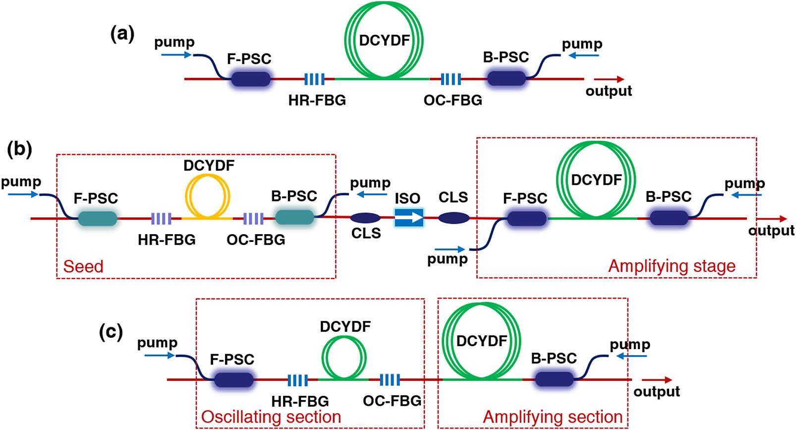
Figure 1.Schematic diagram of the three structures of fiber lasers: (a) fiber laser oscillator based on the FP-fiber cavity; (b) fiber laser amplifier based on the MOPA structure; (c) OAIFL.
In 2018, Shu et al. realized a 2-kW fiber laser output based on an OAIFL, with an O–O efficiency of 81.6% and a beam quality M2 of 1.4, and verified its good anti-back-reflected light characteristics[22]. In addition to the above-mentioned advantages, OAIFL can allow a more flexible arrangement of pump energy between the oscillating section and the amplifying section. Active fibers with different characteristics can be used in the oscillating section and the amplifying section to jointly achieve better output results. In 2019, Tian et al. realized a 1018-nm fiber laser with an output power of 300 W and a beam quality M2 factor of 1.19 based on this structure[23]. By adopting ytterbium-doped fibers with different characteristics in the oscillating section and the amplifying section, high conversion efficiency, good amplified spontaneous emission (ASE) suppression effect, and high beam quality are achieved. At present, the highest power of OAIFL is 2.19 kW of a narrow linewidth laser achieved by Huang et al. in 2019[24]. The 3-dB bandwidth is 86.5 pm with an O–O efficiency of 78.3% and a beam quality M2 of approximately 1.46.
Sign up for High Power Laser Science and Engineering TOC. Get the latest issue of High Power Laser Science and Engineering delivered right to you!Sign up now
In this paper, we designed and realized an OAIFL. Two double-clad ytterbium-doped fibers (DCYDFs) with a core/cladding diameter of 22/400 μm are used as the gain medium, and the length of the active fiber in the oscillating section and the amplifying section is 8 and 22 m, respectively. By reducing the length of the active fiber in the amplifying section, a 3.5-kW near-single-mode (M2 ∼ 1.24) all-fiber laser is realized with an O–O efficiency of 87.0% under the condition of co-/counter-pump power of 256 /3787 W.
2. Experimental setup
The experimental structure of the OAIFL is shown in Figure 2(a). The active fiber used is a DCYDF with a core/cladding diameter of 22/400 μm, and the absorption coefficient for 915-nm pump light is about 0.54 dB/m. The oscillating section of the laser consists of a piece of DCYDF (DCYDF1) with a length of 8 m, an HR-FBG, an output coupler fiber Bragg grating (OC-FBG), and a set of co-pumping sources. The HR-FBG, the OC-FBG, and the active fiber (DCYDF1) together form a resonant cavity to generate the signal. The pump source used for the co-pumping of the oscillating section is five groups of laser diodes (LDs) with a center wavelength around 976 nm and the maximum output power of each group is about 900 W. All the LDs are combined through a (6 + 1) ×1 forward pump/signal combiner (F-PSC). Both the HR-FBG and the OC-FBG have a core/cladding diameter of 22/400 μm and a center wavelength of 1080 nm. The reflectivity of the HR-FBG and the OC-FBG is 99.5% and 9.7% with a 3-dB bandwidth of 3.11 and 1.00 nm, respectively. After the OC-FBG is the amplifying section of the laser composed of a piece of DCYDF (DCYDF2) with a length of 22 m and a set of counter-pumping sources. The pump sources used for the counter-pumping of the amplifying section are five groups of LDs, the same as the LDs used in the oscillating section, and are combined through a (6 + 1) ×1 backward pump/signal combiner (B-PSC). The laser applies the bidirectional pump scheme shown in Figure 2(a) with the co-pumping of the oscillating section and the counter-pumping of the amplifying section. The core/cladding diameters of the output signal fiber and input signal fiber of F-PSC and B-PSC are 22/400 μm and 25/250 μm, respectively. As there is no CLS between the oscillating section and the amplifying section, the residual forward pump light passing through the resonant cavity can be injected directly into the DCYDF2 and the residual backward pump light can also enter the oscillating section. The output laser passes through a CLS and a passive fiber with a length of about 3 m and a core/cladding diameter of 25/400 μm, and then enters the measuring system. The power, the spectrum, the beam quality, and the time domain characteristics of the output laser are measured. The DCYDF1 and the DCYDF2 are coiled on the same water-cooled plate with a figure-of-eight fiber groove as shown in Figure 2(b), and the coiling diameters at both ends of the DCYDF1 (DCYDF2) are 8.5 cm (8.5 cm) and 11.5 cm (12.3 cm), respectively. The smaller coiling diameter of the fiber in the oscillating section causes the large loss of the higher-order mode, and the signal generated in the oscillating section is mainly the fundamental mode. The smaller coiling diameter at both ends of the DCYDF2 also ensures a large enough high-order mode loss in the amplification process, so that a near-single-mode laser can be realized.
![]()
Figure 2.Schematic of the bidirectionally pumped OAIFL: (a) experimental structure; (b) schematic diagram of the fiber groove.
3. Results and discussion
3.1. Experiment results of co-pumping
First, we only turned on the co-pumping of the oscillating section and the experimental results are shown in Figure 3. From the results in Figure 3(a), we can see a good linear relationship between the output power and the pump power with a gradually increasing O–O efficiency. An output power of 1537 W is achieved with an O–O efficiency of about 82.9% when the pump power is 1855 W. At this time, no TMI characteristics were observed in the signal of the photodetector and its corresponding fast Fourier transform (FFT) results, as shown in Figure 3(b). The beam quality factors of the laser at the maximum power shown in Figure 3(c) are
![]()
Figure 3.Experimental results of co-pumping: (a) variation curves of the output laser power and the O–O efficiency with the pump power; (b) signal of the PD at the maximum output power and their FFT results (inset); (c) result of the beam quality
3.2. Experiment results of bidirectional pumping
In order to suppress the SRS, we increased the counter-pump power of the amplifying section, and the experimental results are shown in Figure 4. Limited by the strong SRS (29.92 dB lower than the signal light intensity), the maximum output power is 3124 W under a total pump power of 3572 W (256 W for the co-pumping of the oscillating section and 3316 W for the counter-pumping of the amplifying section), which corresponds to an O–O efficiency of 87.5%. Figure 4(b) shows the signal of the PD and its corresponding FFT results at the maximum power, and no TMI characteristics are observed. Throughout the experiment, the spectrum bandwidth of the output laser gradually broadened, maintaining a good linear relationship with the output power. The 3-dB bandwidth is 1.6 nm at the output power of 188 W, and this value reaches 5.10 nm with a broadening rate of about 0.119 nm/100 W when the output power reaches 3124 W.
![]()
Figure 4.Experimental results of bidirectional pumping: (a) variation curves of the output laser power and the O–O efficiency with the pump power; (b) signal of the PD at the highest output power and their FFT results (inset); (c) spectra at different output powers; (d) measured 3-dB bandwidth at the different output powers.
The emergence of the SRS severely inhibited the scaling of the power. From the analysis of the above results, it can be found that the laser has a high efficiency and no pump light component was observed in the output spectrum. Therefore, the fiber length of the current amplifying section is sufficient. Considering the influence of the fiber length on the SRS, we can reduce the length of the active fiber in the amplifying section to suppress the SRS and achieve a better result. Based on this, after shortening the active fiber of the amplifying section by about 4.4 m, an output of 3517 W with an O–O efficiency of 87.0% is obtained under the condition of a total pump power of 4043 W (256 W for the co-pumping of the oscillating section and 3787 W for the counter-pumping of the amplifying section). Table 1 lists the main experimental parameters before and after the shortening of the fiber in the amplifying section. We can see that the shortening of the fiber caused a slight decrease in the efficiency. At the same power level (∼3100 W), the SRS intensity is reduced by approximately 4.80 dB. The spectrum comparison shown in Figure 5(a) more clearly shows the improvement of the SRS suppression after the shortening of the fiber. It can be found that the SRS intensity is about 23.61 dB lower than the signal light intensity at the maximum power and the 3-dB bandwidth is 5.62 nm. At present, the highest O–O efficiency of an all-fiber laser oscillator based on a common fiber is publicly reported as about 81%[20], and the efficiency of this laser is obviously higher than that of a common fiber-based laser oscillator. The main reason is that there is no CLS between the oscillating section and the amplifying section, and the forward and backward pump light can be fully utilized. The measured M2 factors of
![]()
Figure 5.Experimental results of bidirectional pumping after shortening the active fiber of the amplifying section: (a) spectral comparison before and after the shortening of the fiber; (b) result of the beam quality
| Length of DCYDF1 (m) | Length of DCYDF2 (m) | Output power (W) | Efficiency | SRS intensity (dB) |
|---|---|---|---|---|
| 8.0 | 22.0 | 3124 | 87.5% | 29.92 |
| 8.0 | 17.6 | 3115 | 87.2% | 34.72 |
| 8.0 | 17.6 | 3517 | 87.0% | 23.61 |
Table 1. The main experimental parameters and results before and after the shortening of the active fiber in the amplifying section.
Table 2 lists the main experimental parameters and results of the existing research into the OAIFL which indicates the potential application fields. It can be seen from the table that the choice of the type and the length of the active fiber for the oscillating section and the amplifying section is very flexible, and can be matched and adjusted according to actual needs and experimental results. Our laser has currently the maximum power with the best beam quality and the highest O–O efficiency. An active fiber with a core diameter of 22 μm can achieve better SRS suppression than fibers with a core diameter of 20 μm. Under a proper coiling diameter, it can also increase the loss of higher-order modes and increase the TMI threshold. For current lasers, the SRS is the main factor limiting the power scaling, and many potential factors could be investigated for the purpose of SRS suppression. Before and after the shortening of the fiber in the amplifying section, the O–O efficiency of the laser remained at a relatively high level, indicating that the final fiber length can still ensure sufficient pump absorption. Therefore, the length of the active fiber in the amplifying section can still be reduced for further SRS suppression. In addition, according to the conclusion in the literature[26], a better SRS suppression can be achieved with a shorter fiber in the resonant cavity. The length of the fiber in the current resonant cavity of oscillating section is 8 m, and there is still room for optimization. We can try to shorten the active fiber length in the resonant cavity to suppress the SRS. Finally, the use of fibers with larger core diameters or fibers with a new structure such as spindle-shaped ytterbium-doped fiber with gradual core diameters is also an experimental program with great potential for achieving even higher power levels[27].
| Core/cladding | ||||||
|---|---|---|---|---|---|---|
| diameter of the | Fiber length of | |||||
| oscillating | the oscillating | |||||
| (amplifying) section | (amplifying) | Output | Experimental | |||
| (μm) | section (m) | power (W) | M2 | Efficiency | purpose | Reference |
| 20/400 (20/400) | 1.5 (22.5) | 1570 | 1.36 | 71.4% | Increase the TMI threshold of the fiber oscillator | [ |
| 20/400 (25/400) | 10.0 (14.5) | 2190 | 1.46 | 78.3% | Narrow-linewidth laser | [ |
| 20/400 (20/400) | 2.0 (15.0) | 2031 | 1.40 | 83.6% | Verification of anti-back-reflected light ability | [ |
| 10/130 (20/130) | 1.3 (1.3) | 300 | 1.19 | 79.3% | 1018-nm fiber laser | [ |
| 22/400 (22/400) | 8.0 (17.6) | 3517 | 1.23 | 87.0% | High-power, high-beam-quality laser | This work |
Table 2. Comparison of the main parameters and results of the existing OAIFL.
4. Conclusion
An OAIFL has been successfully achieved, and the output characteristics of the laser were studied in detail. By turning on the co-pumping of the oscillating section and the counter-pumping of the amplifying section at the same time, a 3.5-kW near-single-mode laser output is realized with an O–O efficiency of 87.0%, which is the highest output power of the OAIFL, accompanied with the best beam quality and the highest O–O efficiency. This experiment has verified the good power amplification capability of the OAIFL, which has better SRS suppression capability than the amplifier and higher O–O efficiency than the oscillator under the same conditions. Based on this experiment, the fiber length and parameters can be optimized to achieve a higher-power laser while ensuring high beam quality and high efficiency.
References
[1] D. J. Richardson, J. Nilsson, W. A. Clarkson. J. Opt. Soc. Am. B, 11, 27(2010).
[2] M. N. Zervas, C. A. Codemard. IEEE J. Sel. Top. Quant., 5, 20(2014).
[3] J. W. Dawson, M. J. Messerly, R. J. Beach, M. Y. Shverdin, E. A. Stappaerts, A. K. Sridharan, P. H. Pax, J. E. Heebner, C. W. Siders, C. P. J. Barty. Opt. Express, 17, 16(2008).
[4] T. Eidam, S. Hanf, E. Seise, T. V. Andersen, T. Gabler, C. Wirth, T. Schreiber, J. Limpert, A. Tünnermann. Opt. Lett., 2, 35(2010).
[5] T. Eidam, C. Wirth, C. Jauregui, F. Stutzki, F. Jansen, H. J. Otto, O. Schmidt, T. Schreiber, J. Limpert, A. Tunnermann. Opt. Express, 14, 19(2011).
[6] A. V. Smith, J. J. Smith. Opt. Express, 11, 19(2011).
[7] M. N. Zervas. Opt. Express, 13, 27(2019).
[8] C. Jauregui, C. Stihler, J. Limpert. Adv. Opt. Photonics, 2, 12(2020).
[9] J. R. Marciante, R. G. Roides, V. V. Shkunov, D. A. Rockwell. Opt. Lett., 11, 35(2010).
[10] F. Zhang, Y. Wang, X. Lin, Y. Cheng, Z. Zhang, Y. Liu, L. Liao, Y. Xing, L. Yang, N. Dai, H. Li, J. Li. Opt. Express, 15, 27(2019).
[11] T. Eidam, S. Hädrich, F. Jansen, F. Stutzki, J. Rothhardt, H. Carstens, C. Jauregui, J. Limpert, A. Tünnermann. Opt. Express, 9, 19(2011).
[12] Y. Ye, X. Xi, C. Shi, B. Yang, X. Wang, H. Zhang, P. Zhou, X. Xu. Laser Phys. Lett., 8, 16(2019).
[13] B. Yang, H. Zhang, C. Shi, X. Wang, Z. Pan, Z. Wang, P. Zhou, X. Xu. Opt. Express, 27, 5(2019).
[14] J. Kim, P. Dupriez, C. Codemard, J. Nilsson, J. K. Sahu. Opt. Express, 12, 14(2006).
[15] R. Tao, R. Su, P. Ma, X. Wang, P. Zhou. Laser Phys. Lett., 2, 14(2016).
[16] M. Wang, Y. Zhang, Z. Wang, J. Sun, J. Cao, J. Leng, X. Gu, X. Xu. Opt. Express, 2, 25(2017).
[17] T. Li, W. Ke, Y. Ma, Y. Sun, Q. Gao. J. Opt. Soc. Am. B, 6, 36(2019).
[18] A. Roohforouz, R. E. Chenar, S. Azizi, R. R. N. Abad, K. Hejaz, A. A. Najafi, V. Vatani, S. H. NabaviAdvanced Solid State Lasers. , , , , , , , and , (Optical Society of America, ).(2019).
[19] E. StilesProceedings of the 5th International Workshop on Fiber Lasers. , in (), p. ., 4(2009).
[20] Y. Wang, R. Kitahara, W. Kiyoyama, Y. Shirakura. , , , and , Proc. SPIE , 1126022 ().(2020).
[21] K. Hejaz, M. Shayganmanesh, A. Roohforouz, R. Rezaei-Nasirabad, A. Abedinajafi, S. Azizi, V. Vatani. Appl. Opt., 57(2018).
[22] Q. Shu, C. Li, H. Lin, Z. Huang, B. Wang, Y. Liu, Z. Li, C. Guo, X. Tang, P. Zhao, J. Wang, F. Jing. Chin. J. Lasers, 45(2018).
[23] J. Tian, Q. Xiao, D. Li, Y. Huang, Z. Wang, P. Yan, M. Gong. OSA Continuum, 2, 1138(2019).
[24] Y. Huang, P. Yan, Z. Wang, J. Tian, D. Li, Q. Xiao, M. Gong. Opt. Express, 3, 27(2019).
[25] J. Wang, D. Yan, S. Xiong, B. Huang, C. Li. Opt. Express, 13, 24(2016).
[26] Y. Wang, W. Peng, Y. Sun, C. Zha, T. Li, J. Wu, Y. Feng, Y. Ma, R. Zhu, C. Tang. IEEE Photon. Tech. Lett., 12, 30(2018).
[27] L. Zeng, X. Xi, Y. Ye, H. Zhang, X. Wang, Z. Pan, Z. Wang, X. Xu. Opt. Lett., 20, 45(2020).


Set citation alerts for the article
Please enter your email address

© Copyright 2018-2021 | Chinese Laser Press. All Rights Reserved 沪ICP备15018463号-20