Mohammad Hadi, Farokh Marvasti, Mohammad Reza Pakravan, "Dispersion compensation using high-positive dispersive optical fibers," Chin. Opt. Lett. 15, 030601 (2017)
Copy Citation Text
The common and traditional method for optical dispersion compensation is concatenating the transmitting optical fiber by a compensating optical fiber having a high-negative dispersion coefficient. In this Letter, we take the opposite direction and show how an optical fiber with a high-positive dispersion coefficient is used for dispersion compensation. Our optical dispersion compensating structure is the optical implementation of an iterative algorithm in signal processing. The proposed dispersion compensating system is constructed by cascading a number of compensating sub-systems, and its compensation capability is improved by increasing the number of embedded sub-systems. We also show that the compensation capability is a trade-off between the transmission length and bandwidth. We use the simulation results to validate the performance of the introduced dispersion compensating module. Photonic crystal fibers with high-positive dispersion coefficients can be used for constructing the proposed optical dispersion compensating module.
Since the revolution of fiber optic communications in the 90s, millions of kilometers of optical fibers have been laid all over the world to convey the ever-growing data streams primarily driven by the exponential increase in communicated video and data traffic. This exponential growth in data traffic is met through increasing per-channel bit rates or numbers of accommodated sub-channels using techniques such as wavelength division multiplexing (WDM) or optical orthogonal frequency division multiplexing (O-OFDM)[1–4]. Increasing the per-channel bit rate requires the transmission of narrower optical pulses, which multiplies the signal degradation due to the high amount of accumulated chromatic dispersion during pulse propagation through the optical fiber. This high amount of dispersion may result in inter-symbol interference (ISI), information loss, and an increased bit error rate (BER) value. On the other hand, increasing the number of accommodated sub-channels results in reduced space between adjacent sub-channels, more transmitted optical power, and more sensitivity to destructive fiber nonlinear effects. Consequently, both increasing the per-channel bit rate and the number of accommodated sub-channels lead to excessive sensitivity to certain fiber impairments that degrade the clean transmission of the optical signal[5]. Practically, the increased optical power along with tighter sub-channel spacing and longer transmission distances translate to a trade-off between nonlinear propagation effects and chromatic dispersion in a fiber optic communication system[6]. Today’s advanced optical fibers are designed such that they exhibit finite dispersion in the transmission band. This finite amount of dispersion reduces the growth of nonlinear effects such as four-wave mixing (FWM) and cross-phase modulation, which are particularly deleterious in WDM and O-OFDM communication systems[7,8]. In order to resolve the ISI and BER forced by the mentioned finite amount of dispersion, proper dispersion compensating techniques have been proposed to compensate for the accumulated dispersion in the propagated pulse through the optical fiber. Compensation can be achieved in the optical domain by the use of different dispersion compensation devices, such as dispersion compensating gratings, dispersion compensating fibers (DCFs), dispersion compensating arrayed waveguides, etc.[5,9,10]. Electronic dispersion compensators are also proposed to compensate for the accumulated dispersion in the electrical domain[11,12].
Conventional DCFs are suitably constructed optical fibers with an appropriate refractive index profile such that they exhibit the desired dispersion value at the wavelength of operation. Since the dispersion coefficient of the transmission optical fiber is usually positive, the conventional DCF should exhibit a negative dispersion coefficient. They should also have dispersion slope matching, low bend loss, low propagation loss, and a relatively large mode effective area[5,13]. Design trade-offs to meet some of these requirements are necessary, e.g., a small dispersion coefficient is usually characterized by a small mode effective area and, consequently, large nonlinear effects and vice versa[5,6,9,13]. In this Letter, we take the opposite direction and show how an optical fiber with a high-positive dispersion coefficient can also be used to compensate for the dispersion. In fact, our compensating procedure is an adoption of an iterative method in signal processing that uses a given system to implement its inverse system[14]. The proposed dispersion compensating structure is a cascade repetition of a sub-system, and its compensation capability is improved by a higher number of cascaded sub-systems in the structure. Furthermore, the capability of the proposed dispersion compensating technique is a trade-off between the transmission length and bandwidth. It is noteworthy that the introduced structure can simultaneously compensate for the dispersion, dispersion slope, and other high-order dispersions. Photonic crystal fibers (PCFs) with high-positive dispersion and low attenuation coefficients can be considered as a main candidates for constructing the offered compensating module[10,15,16]. The high-positive dispersion and low attenuation coefficients of these PCFs improve the compensation ability of our structure by providing dispersion compensation with lower latency, attenuation, and sensitivity to nonlinear effects in comparison with conventional DCFs.
To proceed, we present a brief survey of chromatic dispersion and its mathematical model. Following a concise review of the mentioned iterative method, we introduce and analyze our new dispersion compensating system and validate its performance using the simulation results.
Sign up for Chinese Optics Letters TOC. Get the latest issue of Chinese Optics Letters delivered right to you!Sign up now
One of the most significant impairments in fiber optic communication systems is chromatic dispersion. The light pulses propagating along the optical fiber become distorted because the different spectral components of the signal travel at different speeds and hence experience different propagation delays during transmission. This means those parts of the signal will reach the receiver at different time instants, which results in temporal pulse distortion and broadening. The dispersion is characterized by the parameter , which describes how the pulse is broadened. Assuming that the fiber is a cylindrical dielectric waveguide along the -axis, the wave propagation in the frequency domain along the positive -coordinate is given by[6,9,17]where and are pulse fields at angular frequency and distances 0 and with respect to the origin, respectively, and is the fiber frequency-dependent propagation constant. Assuming that the spectral width is much smaller than the carrier frequency , the Taylor series expansion of the propagation constant around is where the series coefficients are written as , in which stands for -th order derivative with respect to . The group delay per unit of length is . The first term of Eq. (2) represents a frequency independent phase rotation that can be disregarded for the propagation of the pulse. The second parameter is equal to the group delay per unit of length at the carrier frequency and also equals the inverse of the group velocity at the carrier frequency, i.e., , , where is the frequency-dependent refractive index. The third term of Eq. (2) describes first-order chromatic dispersion and, sometimes, it is called the group velocity dispersion. Chromatic dispersion parameter is responsible for the linear variation of the group delay with the frequency. Commonly, the chromatic dispersion parameter is characterized in terms of instead of : where D is the mentioned dispersion coefficient, and its unit is usually expressed as ps/nm/km. Other parameters , are related to high-order dispersions and are usually neglected in comparison with the main dispersion parameter . Clearly, the effect of dispersion on the pulse propagation through the optical fiber is totally characterized by the dispersion transfer function ,
For a better understanding of the chromatic dispersion effect in the time domain, we can study the propagation model of Gaussian pulses inside the optical fiber. Assume that initial field of the pulse is , where is the peak amplitude, and is the half-width at the intensity point. As shown in Ref. [9], during its propagation along the fiber, the Gaussian pulse keeps its Gaussian shape; however, the pulse width increases with the propagation distance , resulting in a broadening factor given by where represents the received half-width defined similar to .
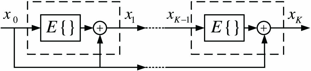
The iterative method is a systematic technique in which successive operations of a given operator are used to provide an estimate of its corresponding inverse operation[14]. Consider an arbitrary operator named and let be the identity operator. Defining as error operator, means consecutive operations of the error operator. It can be shown that , the inverse of the operator , can be calculated as follows: provided that is linear and its operator norm is less than 1[14]. For sufficiently large values of , Eq. (6) provides an approximation of the inverse operator . Figure 1 shows a systematic realization for Eq. (6) that is referred to as direct implementation. Consider as the input signal (operand). According to Fig. 1, and, therefore, we can recursively write
Figure 1.Direct implementation of the iterative method, which is a cascaded repetition of the highlighted part. Each highlighted part is an error operator followed by an add operation.
Finally, after stage , which is the approximate implementation of Eq. (6). As shown in Fig. 2, the inverse operator can also iteratively be realized by feedbacking the output of the highlighted part in Fig. 1 to its input. Feedback implementation is suitable for digital systems in which the number of iterations in a feedback loop can easily be controlled, while direct implementation is usually used for analog systems. In the digital implementation of the iterative method, signal , which is a vector of the input signal samples, is received and then cycles times in the shown loop of Fig. 2. After cycles, is transferred to the output and a new vector of the input signal samples is fed to the structure[14]. To change the convergence time or extend the convergence region, a scaling factor can be included in the definition of the error operator . Increasing decreases the convergence time at the cost of reducing the convergence region[14]. The iterative method has been successfully used for interference cancellation in optical code division multiple access systems via optical logic gate elements. Furthermore, its applications for mitigating the peak to average power ratio problem in optical OFDM systems are evolving[18,19].
Figure 2.Feedback implementation of the iterative method, which is a closed-loop system constructed of the highlighted part of Fig. 1. The input signal should cycle times in the feedback loop to provide an output equivalent to the output of the direct implementation, with repetitions of the highlighted part.
Now, consider the structure shown in Fig. 3. This structure is an optical adoption of the introduced iterative method that implements the inverse of the chromatic dispersion transfer function using high-positive dispersive optical fibers. Note that the chromatic dispersion transfer function is a linear operation and, consequently, its inverse operation can be realized using the iterative method. Sub-system gets an input optical signal, divides it between two optical fibers, and constructs the output optical signal by subtracting the outputs of the optical fibers[6,20,21]. We assume the optical fiber in the up branch of the sub-system is an ordinary optical fiber with characterizing parameters , , and length , while the optical fiber in the down branch is a special optical fiber with characterizing parameters , and length such that , and , . A well-designed high-positive dispersive PCF can satisfy the requirements of the optical fiber in the down branch of the sub-system. If the attenuator in the down branch has an attenuation coefficient , the transfer function of the sub-system is given by
Figure 3.Block diagram of the proposed dispersion compensating structure, including 2 cascaded sub-systems .
In Fig. 3, the optical fiber below each embedded sub-system has the same characterizing parameters as the optical fiber in the up branch of the sub-system. Referring to Eq. (12) and assuming cascaded copies of the analyzed sub-system, one can easily check that the total transfer function of the system is simplified as
For a sufficiently large number of cascaded sub-systems and for , which is the desired inverse transfer function of the chromatic dispersion with a causal delay coefficient.
Assume we want to compensate for the chromatic dispersion of an optical fiber with characterizing parameters , and length . If we set , and , the proposed structure can totally remove the dispersion if
By neglecting high-order dispersion coefficients , against the main dispersion coefficient , Eq. (15) implies that we have the following trade-off between the transmission length and bandwidth for a stable dispersion compensation:
It is noteworthy that the optical amplifier of the proposed structure can be merged with the receiver amplifier and its other parts can totally be constructed using passive optical elements. Furthermore, the length of the required compensating fibers , the compensation delay, and the compensation attenuation are reduced for higher values of .
Figure 4 shows the two-dimensional region of transmission length (in logarithmic scale and units of km) and bandwidth (in linear scale and units of GHz) values for which the introduced system can be stable and compensate for the dispersion. We refer to this region as the convergence region. As illustrated, the boundary of this region is governed by the explicit trade-off between the transmission length and bandwidth in Eq. (16), and its area is extended for lower values of dispersion coefficient or attenuation coefficient . Now, consider a sinc-shaped optical pulse with a given zero-to-zero pulse width and its corresponding bandwidth . This pulse is conveyed by a carrier wavelength over an optical fiber having the second-order dispersion parameter and length . We use the proposed system to compensate for the accumulated dispersion in the sinc-shaped pulse propagated through this optical fiber. Figure 5 shows the simulated broadening factor of the compensated pulse (i.e., the ratio of the received pulse width to the transmitted pulse width) in terms of the number of embedded sub-systems in the compensating system for various values of and attenuation coefficient . Clearly, the compensation performance is increased for higher numbers of cascaded sub-systems. Furthermore, a pulse with a lower bandwidth and transmission distance needs a lower number of sub-systems to get a desired dispersion compensated level. The simulation results also show decreasing the attenuation coefficient decreases the convergence speed, but as interpreted from Fig. 4, this can extend the convergence region to include a desired pair of transmission length and bandwidth.
Figure 4.Two-dimensional region of transmission length and bandwidth values for which the proposed system can stably compensate for dispersion.
Figure 5.Broadening factor for a sinc-shaped optical pulse conveyed by carrier wavelength in terms of the number of cascaded sub-systems in the compensating structure for various values of and attenuation coefficient .
Assume that we desire to compensate for the accumulated dispersion of a single-channel optical signal with a 3 GHz bandwidth and a 1550 nm carrier wavelength that propagates through a 130 km standard single-mode optical fiber such that a broadening factor of 1.1 is achieved at the receiver side. Since , Fig. 5 shows that our proposed dispersion compensating module, including 1 embedded sub-system, can provide the desired compensated broadening factor. If (or, equivalently, ), the signal propagation path of the proposed compensating structure will be around 1 km. As the simulation results show, the desired level of the compensated broadening factor can also be obtained using a sample DCF with and an approximated propagation path of 7 km[13]. The propagation path in the proposed module is shorter than its counterpart DCF, and hence, it has a potential to provide lower attenuation and delay during the compensation process.
In conclusion, we take the opposite direction with respect to the conventional DCFs and show how an optical fiber with a high-positive dispersion coefficient is used for dispersion compensation. We propose an optical structure based on a well-known iterative algorithm in signal processing in which the dispersion inverse transfer function is implemented using high-positive dispersive optical fibers. We show that the dispersion compensation capability of the proposed module is a trade-off between the transmission length and bandwidth and is enhanced for the compensating structure, including more dispersion compensating sub-systems. We also specify how system parameters should change to stabilize or speed up the system performance.
Generally, the concepts and ideas behind the proposed structure can be used in developing other innovative optical modules, such as optical filters and other optical impairment compensating structures. It is noteworthy that the optical implementation of the proposed structure can be facilitated using progressing technologies such as photonic integrated circuits[22], optical analog field programmable gate arrays[23], optical logic gates[18], and architectures on demand[6]. In addition, one may work on electronic dispersion compensation using the iterative method. Clearly, implementation of the iterative method in electronic domain is more straightforward than its equivalent optical implementation.
Mohammad Hadi, Farokh Marvasti, Mohammad Reza Pakravan, "Dispersion compensation using high-positive dispersive optical fibers," Chin. Opt. Lett. 15, 030601 (2017)