• Chinese Optics Letters
  • Vol. 16, Issue 6, 060603 (2018)
Chaoyi Li1、2, Junming An1、2、*, Jiashun Zhang1, Liangliang Wang1, Jianguang Li1, Yue Wang1, Xiaojie Yin1, Hongjie Wang1, and Yuanda Wu1、2
Author Affiliations
  • 1State Key Laboratory of Integrated Optoelectronics, Institute of Semiconductors, Chinese Academy of Sciences, Beijing 100083, China
  • 2College of Materials Science and Opto-Electronic Technology, University of Chinese Academy of Sciences, Beijing 100049, China
  • show less
    DOI: 10.3788/COL201816.060603 Cite this Article Set citation alerts
    Chaoyi Li, Junming An, Jiashun Zhang, Liangliang Wang, Jianguang Li, Yue Wang, Xiaojie Yin, Hongjie Wang, Yuanda Wu. 4 × 20 GHz silica-based AWG hybrid integrated receiver optical sub-assemblies[J]. Chinese Optics Letters, 2018, 16(6): 060603 Copy Citation Text show less
    Configuration of ROSA. (a) Circuit diagram. (b) Package schematic.
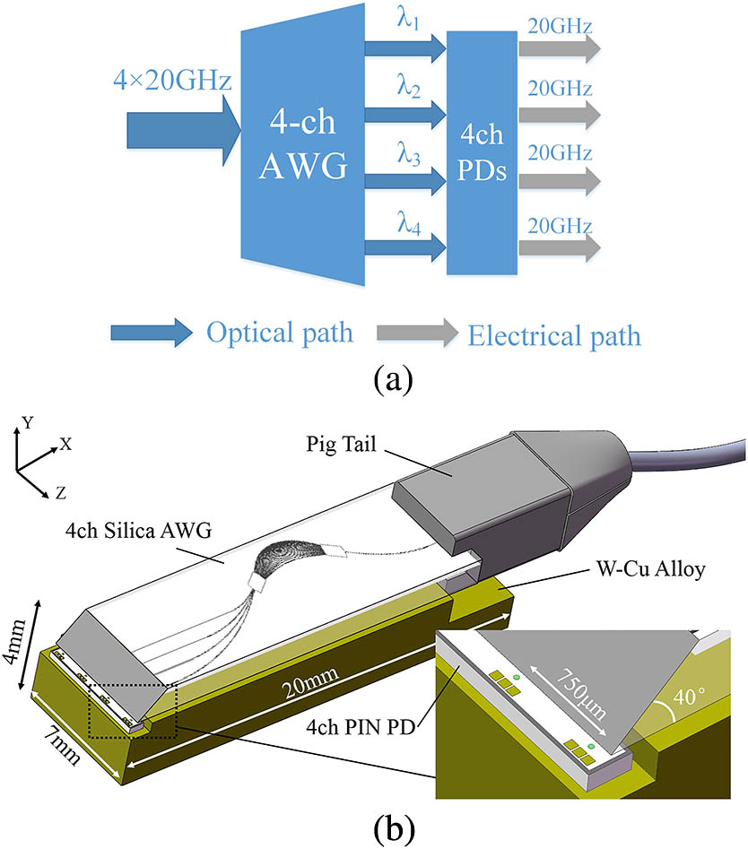
    Fig. 1. Configuration of ROSA. (a) Circuit diagram. (b) Package schematic.
    Relationship between the effective refractive index (neff) and waveguide width.
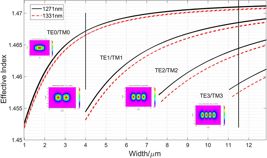
    Fig. 2. Relationship between the effective refractive index (neff) and waveguide width.
    Longitudinal section of propagation simulation with an angle of 40°.
    Fig. 3. Longitudinal section of propagation simulation with an angle of 40°.
    Transmission loss (a) at different distances and wavelengths under the 40° angle and (b) at different angles and wavelengths under 20 μm distance. (The simulated light source contains both the polarizations simultaneously.)
    Fig. 4. Transmission loss (a) at different distances and wavelengths under the 40° angle and (b) at different angles and wavelengths under 20 μm distance. (The simulated light source contains both the polarizations simultaneously.)
    Spot profiles under the 20 μm transmission distance at (a) 45°, (b) 42°, (c) 40°, and (d) 38°.
    Fig. 5. Spot profiles under the 20 μm transmission distance at (a) 45°, (b) 42°, (c) 40°, and (d) 38°.
    SEM photographs of (a) single-mode waveguides and (b) a multimode waveguide.
    Fig. 6. SEM photographs of (a) single-mode waveguides and (b) a multimode waveguide.
    Photograph of ROSA.
    Fig. 7. Photograph of ROSA.
    ROSA responsivity in (a) CWDM and (b) LAN-WDM (gray areas indicate CWDM and LAN-WDM grid).
    Fig. 8. ROSA responsivity in (a) CWDM and (b) LAN-WDM (gray areas indicate CWDM and LAN-WDM grid).
    Linearity in CWDM and LAN-WDM.
    Fig. 9. Linearity in CWDM and LAN-WDM.
    Small signal frequency responses in CWDM and LAN-WDM.
    Fig. 10. Small signal frequency responses in CWDM and LAN-WDM.
    TypeResponsivity (A/W)1 dB Bandwidth (nm)Crosstalk (dB)3 dB E-O Response (GHz)
    CWDM in Ref. [13]0.30.4>10<20>9
    Our work0.4>15<2020
    LAN-WDM in Ref. [14]0.5>2.5<3025 (Gb/s)
    Our work0.4>3<2020
    Table 1. Performance Comparison of ROSAs
    Chaoyi Li, Junming An, Jiashun Zhang, Liangliang Wang, Jianguang Li, Yue Wang, Xiaojie Yin, Hongjie Wang, Yuanda Wu. 4 × 20 GHz silica-based AWG hybrid integrated receiver optical sub-assemblies[J]. Chinese Optics Letters, 2018, 16(6): 060603
    Download Citation