We present the investigation on deformation of orbital angular momentum (OAM) modes in bending ring-core fibers (RCFs) with different structure sizes through numerical and experimental studies. The effective refractive index differences of even and odd fiber eigenmodes, which constitute modes, induced by RCF bending and their impacts on the mode intensity distributions are analyzed. Bending experiments are also carried out on three different RCFs, and the results match well with simulation values. It is found that RCFs with smaller inner and outer radii show preferable tolerance to the fiber bending.
An orbital angular momentum (OAM) beam owning a helical phase front of , where is the azimuthal angle, and , known as the topological charge, can take arbitrary integer values, has drawn close attention in a variety of fields, such as optical trapping[1,2], optical tweezers[3], and quantum optics[4]. The unique property of inherent orthogonality of OAM beams with different topological charges enables an additional degree of freedom for data multiplexing, which can serve as a new solution to the incoming communication capacity crunch. The recent past has seen an explosion of interest about OAM modes multiplexing in both free-space and fiber-optical communication[5–7].
Remarkably, the transmission distance of the OAM mode in fiber has achieved 3.6 km with an integrated optical vortex emitter in Ref. [8]. As the OAM mode can be represented by -phase-shifted linear combination of the even and odd hybrid electric (HE or EH) vector modes, a series of ring-core fibers (RCFs) are designed to suppress the degeneration of TM, TE, HE, and EH modes in the same mode groups and support the transmission of OAM modes[9–13]. An inevitable problem with an RCF is the fiber bending, thus, the circular symmetrical refractive index distribution structure is destroyed, resulting in the OAM mode deformation and the decrease of the signal-to-noise ratio in the RCF communication link.
In 2015, Ramachandran et al. investigated the stability of different order OAM modes under bend perturbations within an RCF[14]. Wang et al. proposed using the effective refractive index difference of even and odd fiber eigenmodes to characterize the bending performance of the RCF[15]. However, the variations of the OAM mode during transmission along with bending the RCF is still unclear, and the bending properties of RCFs with different fiber structure sizes need to be studied. Investigation on the deformation of OAM modes in bending RCFs has guiding significance for the design of bent-resistant OAM transmission fibers and the application of OAM fibers in the fiber sensing field[16].
Sign up for Chinese Optics Letters TOC. Get the latest issue of Chinese Optics Letters delivered right to you!Sign up now
In this Letter, by numerical analysis and experimental test, we study the deformation of modes in bending RCFs with different structure sizes. We concentrate on the distortion of mode intensity distributions caused by RCF bending and analyze the variation as transmitted along the bending fiber. While the effective refractive indices of the even and odd modes, constituting the modes, separate from each other as a result of bending induced birefringence, we quantitatively study the effective refractive index differences between the two eigenmodes in bending RCFs with different structure sizes. Besides, bending experiments are carried out on three RCFs, and the measured results present good agreement with simulated predictions, demonstrating the validity of our analysis.
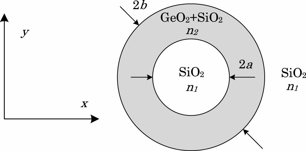
The cross-section and profile of the RCF is shown in Fig. 1, where the inner core radius and the outer core radius are and , and the refractive indices of the cladding and ring core are and , respectively. The normalized frequency is defined as , where is the wavelength, and the diameter ratio is set as . The material of the center and cladding is silica with at 1.55 μm, while the ring core is set to be -doped silica owning its refractive index of , which corresponds to a 20% molecular fraction doping of in [17]. Numerical calculations are done by the finite element analysis with the COMSOL software package.
Figure 1.Schematic diagram of the RCF cross-section.
In order to fix the fiber structure parameters supporting modes, the variables of and are swept to calculate the effective refractive index difference () between adjacent modes. We plot a colormap of the minimum between adjacent modes ( and , and ) as a function of the parameters and , as shown in Fig. 2. The cut-off lines for all of the modes among the calculation region are also given. Point A of and was chosen as the fiber structure used to do the analysis below.
Figure 2.Colormap of minimal between adjacent modes as a function of and . The curves show the corresponding cut-offs for each mode in the calculation region.
When the fiber remains strictly straight, the intensity distributions of the first higher-order eigenmodes show circularly symmetric patterns, as seen in Fig. 3(a), where arrows denote the direction of the electrical fields. The -phase-shifted linear combination of the degenerate pair modes, namely , constitutes the mode. Assuming that the RCF is bent to the negative direction of the axis, the bending gives rise to changes of the refractive index of the fiber materials, thus, the circular symmetry of the refractive index profile of the RCF will be destroyed. The refractive index profile of the bending fiber can be described as where is the refractive index profile of the straight fiber, and is the bending radius[18]. As slightly decreases, for instance to 10 mm, the eigenmode profiles distort from a ring shape into linear polarization (LP)-like intensity distributions. With further decreasing to 6 mm, the modes transform into LP modes with greater than 99% modal power linearly polarized along the or direction[19,20]. However, the induced LP modes, expressed as LP_I modes, is asymmetric in the direction in the bending fiber, resulting in the asymmetry of the composite mode of , as shown in Figs. 3(b)–3(c). Additionally, the asymmetry of the composite mode directly results in the decrease of the mode purity[21].
Figure 3.Intensity distributions and electrical field orientations for the first higher-order eigenmodes, along with intensity and phase distributions for the composite modes in the RCF with different bending radii . (a) Straight fiber, (b) , and (c) .
Pursuant to the birefringence theory, bending induced stress anisotropy tends to increase the between two modes oriented along the major axis ( axis in this Letter) and minor axis ( axis), respectively[22]. As decreases, the even and odd modes evolve into even and odd modes with different spatial field distributions, producing a separation between the of the and modes, as shown in Figs. 4(a) and 4(b). For modes having same spatial field distribution yet different electrical field directions ( and , and ), the diminishes with the decrease of , but remains among the region of .
Figure 4.(a) Effective refractive indices and (b) effective refractive index difference as a function of bending radius .
In a strictly straight RCF, the and modes experience the same phase shift during transmission for sharing the same . That is not the case with a bending fiber in which the of the two modes are separate from each other. Since bending is a lengthwise perturbation, there is an accumulation of phase difference between the two modes during transmutation along the bending fiber. The composite mode of will be converted to the mode after being transmitted in the bending RCF for a specific length[23,24], as shown in Fig. 3. The specific length is defined as the conversion length by the following formula: With the transmission in the bending RCF for , the OAM mode gains enough perturbations to distort into the LP-like mode, thus, the conversion length is in proportion to the resistance to the bending capability of the RCF.
Figure 5 shows as a function of for five fibers with different structure sizes corresponding to the 5 points (A, B, C, D, and E) in Fig. 2. The value of decreases along with the increase of , while the outer core radius stays the same from A to C. Likewise, decreases with the increase of (as well as ) when remains unchanged from C to E. Larger values of indicate smaller between the two modes of and , and feature stronger tolerance to the fiber bending effect[15]. Therefore, the increases of the inner and outer radius can weaken the anti-bend performance of the RCF. To design an RCF supporting modes, the optimum fiber parameters selection region is between the two cut-offs of and modes, while satisfying simultaneously, as shown in Fig. 2, while the fibers with smaller structure parameters under the above condition own better anti-bending performance.
Figure 5.Conversion length as a function of bending radius for different and .
To investigate the bending performance of the RCF experimentally, a group of three RCFs has been fabricated in our laboratory at FiberHome with a modified chemical vapor deposition (MCVD) process and a fiber drawing tower. Figure 6(a) shows a microscope image of the cross-section for fiber 1. Detailed geometry parameters and material refractive indices (at 1.55 μm) for the three fibers are given in Table 1, where is the fiber cladding diameter. All three of the RCFs have been experimentally verified to support the transmission of the modes at 1.55 μm in an RCF test system, as shown in Fig. 7(a), without the bend-post. Representative measurements for fiber 1 are presented in Fig. 6(b). The intensity profiles and interference patterns for the and modes are obtained after a 2 m transmission, and stable intensity profiles after a 1 km RCF link has also been realized[24,25].
Figure 6.(a) Optical microscope image of fiber cross section for fiber 1. (b) Intensity profiles and spiral interference patterns for modes after propagating 2 m in fiber 1.
The RCFs of 3 m long are used in the bending tests. As shown in Fig. 7(b), bending is introduced by wrapping the RCF around bend-posts of different radii, which is identical to the measurement of bending performance for a standard monomode fiber[26,27]. The bending radius is equal to the radius of the bend-post, and is the bending length. According to the measurement of bending angle and the relationship of , the value of is obtained. Figure 7(c) shows the intensity profiles and interference patterns of fiber 1 with a bending radius and a different bending length. The OAM mode can be well transmitted through a straight RCF with a doughnut shape output intensity profile and a spiral interference pattern. As is increased to 20 mm, deformations occur in both intensity and interference outputs. When the bending length reaches the value of , the distribution of the intensity output meets with the numerical results shown in Fig. 3(c).
Figure 7.(a) Experimental setup of the bending test. LD, semiconductor laser; CL, fiber collimator; BE, beam expander; Pol, polarizer; M, mirror; SLM, liquid crystal spatial light modulator; QWP, quarter-wave plate; LE, lens; HWP, half-wave plate; BS, non-polarizing beam-splitter. (b) Bend-post of the RCF. is the length of the bending section, is bending angle, and is the bending radius. (c) Output intensity profiles and corresponding interference patterns of fiber 1 for straight fiber, and , and and , respectively.
The conversion lengths versus the bending radii at 1.55 μm for the three RCFs have been measured and simulated, as shown in Fig. 8. During the course of the experiments, the section of fiber outside of bending part might not remain absolutely straight, which will cause measuring errors. The strain and stress between the bending part and bend-post can also give rise to uncertainty of the measurements. Twenty repeated measurements at each bending radius are averaged as the final value, and the error bars are defined as the standard deviations of the 20 data, which quantitatively represent measurement fluctuations within during the whole data acquisition process. It can be seen that the measured values and simulated results are well matched. The experiments demonstrate that tends to be larger for the RCF with a smaller and . Hence, fiber 1 owns optimal anti-bend performance for its minimum ring-core structure sizes of and among the three fibers, which corresponds to the conclusion above.
Figure 8.Experimentally measured and simulated values of bending lengths versus bending radii for three RCFs.
In this Letter, we focus on the deformation of modes induced by bend perturbations in RCFs with different structure sizes. The distortions of intensity distributions of the first higher-order eigenmodes and the mode variations during transmission in a bending RCF are investigated. As the effective refractive indices of the even and odd modes separate from each other with bending induced birefringence, is used to study the bending properties of RCFs. It is found that RCFs with smaller inner and outer radii own better anti-bending properties. We experimentally measure the conversion length of three RCFs with different structure parameters and demonstrate a good consistency of the experiment values and simulation results. This analytical method targets applications in the design of the OAM fiber with robust anti-bending performance and a highly sensitive RCF bending sensor, which are still under study.