
Xiangzhi Xie, Jilong Li, Feifei Yin, Kun Xu, Yitang Dai, "Low-latency full-field temporal magnification based on spectral compression," Photonics Res. 9, 2494 (2021)
- Photonics Research
- Vol. 9, Issue 12, 2494 (2021)
Abstract
1. INTRODUCTION
Real-time measurements for optical signal that have irregular and ultrafast dynamics over a large time-scale require a high temporal resolution that exceeds the speed and capacity of a conventional digital signal processor. Extensive efforts have been directed to the realization of photonics-assisted methods, which are used to slow down the ultrashort events and overcome the speed limitation of electronic digitizers. The photonics-assisted methods have achieved remarkable success in the observation of transient phenomena in recent years [1–11]. Temporal magnification is one of the most outstanding photonics-assisted schemes for the measurement of rare nonstationary events, where the duration of a signal envelope is greatly stretched [12]. A typical temporal magnification system consists of a time lens and dispersive elements [13]; the signal is prestretched by the first dispersive element and then pre-chirped by the time lens to acquire a temporal quadratic phase; finally, the envelope of an optical signal is magnified after propagation in the second dispersive element. The sampling rate of an analog-to-digital converter (ADC) can be effectively improved by temporal magnification [14–18]. Because the duration of an ultrashort nonstationary signal is greatly extended, continuous measurements can be realized. The inherent physics of transient phenomena, such as optical rouge waves [2–4], soliton dynamics [8], and supercontinuum [11], have been well explored by the temporal magnification method.
Low latency is a critical requirement in the capture of ultrafast dynamics, which can effectively avoid information loss in the analysis process. Unfortunately, the propagation delay introduced by dispersive elements may impair real-time performance of the observation. In addition, the complete picture of a variety of fundamental phenomena needs to be drawn with both phase and amplitude, while the dispersion-based schemes only focus on magnification of the signal envelope. The realization of large temporal magnification ratio is dependent on large dispersive elements. Only the optical fiber is the suitable dispersion medium for the magnification of a broadband optical signal, while the accompanying transmission delay inevitably affects the system’s real-time performance. For example, a spool of dispersion compensation fiber (DCF) with dispersion of
Moreover, real-time phase measurement remains an open challenge in conventional dispersion-based schemes. The secondary phase distortion caused by dispersion cannot be avoided in principle. Additional digital signal processing (DSP) is necessary for the recovery of phase, where the processing delay greatly limits the analysis speed and makes it not competitive in the capture of ultrafast dynamics. In Ref. [8], the simultaneous use of temporal magnification and dispersive Fourier transform enables the recording of the envelope and spectrum of the signal at the same time. The Gerchberg–Saxton algorithm is addressed to recover the optical phase from time-domain and frequency-domain measurements [19]. The reconstruction of the amplitude and phase provides insight into the ultrafast dynamics in optics. However, the digital signal processing delay may become an obstacle to the continuous observations of irregular signals. In Ref. [9], soliton dynamics in optical microcavities are observed by optical sampling and electric-field cross-correlation, while it is targeted at the measurements of quasi-periodic signals.
Sign up for Photonics Research TOC. Get the latest issue of Photonics Research delivered right to you!Sign up now
In this paper, a dispersion-free real-time full-field measurement scheme is proposed, and the characterization for a variety of transient complex optical signals is experimentally demonstrated. Unlike the dispersion-based methods, this solution takes advantage of bandwidth compression to achieve temporal magnification. The bandwidth compression relies on the Vernier effect, where the free spectral range (FSR) of the periodic optical filter and time lens is slightly detuned. The bandwidth compression is divided into two steps: the optical signal under test is spectrally sampled by a periodic optical filter; then, the discrete spectral components are injected into a time lens and optical waveshaper, which brings different spectral components together and coherently compresses the signal bandwidth. Fortunately, the optical phase is preserved during the bandwidth compression, which enables the recovery of the phase information without relying on complex algorithms. Experimentally, real-time measurements for picosecond optical pulses with a complex envelope are demonstrated, where both phase and amplitude are well recovered. Because the proposal eliminates the dependence on dispersion elements, an integrated temporal magnification system could be expected in this method.
2. PRINCIPLE
Our proposal uses coherent temporal magnification to realize the observation of an ultrafast transient signal. Compared with the conventional temporal magnification method, our proposal no longer requires a dispersion medium and can achieve the coherent temporal magnification (both phase and amplitude). The configuration of the conventional temporal magnification scheme is shown in Fig. 1(a). The magnification of the temporal waveform can be achieved if
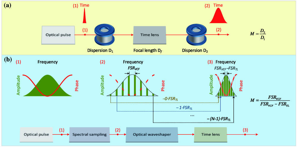
Figure 1.(a) Configuration of the conventional temporal magnification scheme.
![]()
Figure 2.Experimental setup for the real-time full-field measurements. A programmable laser is used to produce ultrafast optical signals with specific amplitude and phase characteristics. MZM, Mach–Zehnder modulator; PM, phase modulator; CW laser, continuous-wave laser; BPD, balanced photodetector. The time lens consists of an MZM and two PMs.
![]()
Figure 3.Relationship between the magnification factor and the FSR difference. (a), (b), and (c), respectively, represent the output temporal waveform when
The spectral compression is equivalent to the magnification of a temporal waveform, which can be expressed as
Here,
Equation (4) suggests that the frequency interval of the spectrum gathering position is
Frequency of the
The operation bandwidth of the proposed system is mainly determined by the convergence ability of the time lens to different frequency components. The operation bandwidth of the system is written as
An optical loss is introduced by the spectral sampling and insertion loss of VCF. The loss of spectral sampling can be estimated by the sampling duty cycle and shape of the sampling function. Because the signal and noise are simultaneously filtered, the signal-to-noise ratio (SNR) is not deteriorated. The SNR is mainly affected by the insertion loss of VCF (around 4 dB). An optical amplifier is employed to compensate the optical loss of the sampling process, which contributes to the maintenance of sensitivity after propagation in subsequent optical devices.
The compressed spectrum is formed by the coherent synthesis of multiple frequency components with a discretization step of
3. EXPERIMENTAL RESULTS
The experimental setup of the proposed dispersion-free temporal magnification scheme is illustrated in Fig. 2. The programmable laser is used to generate an ultrafast optical signal with specific amplitude and phase characteristics. The programmable laser is composed of a femtosecond laser, an MZM, and an optical waveshaper (Finisar, WaveShaper 1000s). A sequence of optical pulses with a repetition rate of 100 MHz and duration of 80 fs is generated by femtosecond laser (ELMO, femtosecond fiber laser). A series of pulses produced by a pulse pattern generator (Agilent, N4951A) is modulated on the optical pulse sequence, under carrier suppression situation, to reduce the repetition rate of the optical pulses. The repetition rate and duration of the RF pulses are 10 MHz and 10 ns, respectively, and the pulse peak is 1 V. Thus, the optical signal with a repetition rate of 10 MHz is generated, and the optical waveshaper is employed to edit the phase and amplitude of the input spectrum. The Vernier comb filter (VCF) is realized by a fiber Fabry–Perot interferometer (FFPI) with FSR of 10.22 GHz. The transmission peak is with the Lorentz shape, and its 3 dB bandwidth is 50 MHz. The time lens consists of an MZM and two PMs. The MZM is biased at the maximum point of the transfer function, where frequency of the RF source varies in different cases; the power of the RF source is 23 dBm. Two PMs are modulated by a single-tone signal; the frequency is twice that of the MZM. The driving power of each PM is set as 30 dBm (1 W), and 40 flat lines in amplitude frequency response within 3 dB bandwidth are obtained. More details of the lossless equalization for the frequency response of the time lens can be referred to in Ref. [20]. Theoretically, the operation bandwidth of the system is 408.8 GHz. The time lens focal dispersion can be expressed as
The experimental results of temporal magnification for an ultrafast Gaussian pulse, with 3 dB bandwidth of 300 GHz, are illustrated in Fig. 3. The input optical pulse is estimated by numerical simulation, and its duration is around 2.9 ps. Experimentally, the optical pulse is generated by an optical waveshaper, where the pulse produced by a femtosecond laser is filtered by the optical waveshaper with a Gaussian shape of 300 GHz. The value of
![]()
Figure 4.Real time full-field measurements for intensity-modulated spectrum. (a) and (b), respectively, represent the comparison of the input pulse (numerical) and output pulse (measured), corresponding to the FSR difference of 140 and 120 MHz. The dotted line represents the input waveforms obtained by numerical simulation; the solid line represents the experimental results. Dark blue line: intensity of temporal waveform. Orange line: phase of temporal waveform. (c) Measured spectrum of input optical signal. (d) and (e), respectively, represent the output spectrum when the FSR difference is 140 and 120 MHz.
Real-time full-field measurements for the intensity-modulated spectrum are shown in Fig. 4. The input spectrum is generated by the femtosecond laser and optical waveshaper. The input spectrum is composed of two Gaussian shapes with 3 dB bandwidth of 40 GHz, and the frequency interval between the Gaussian peaks is 250 GHz. The phase of each Gaussian shape is linear. The numerical results of the input waveform are expressed by dotted lines in Figs. 4(a) and 4(b). Phase of the input waveform is similar to the binary phase-shift keying signal, where the phase value changes back and forth between 0 and
In order to further verify the ability to restore the phase of an optical signal, real-time full-field measurements for a phase-modulated spectrum are performed. The bandwidth of the input spectrum is 300 GHz, and its phase characterization can be expressed as
![]()
Figure 5.Real-time full-field measurements for phase-modulated spectrum. (a) and (b), respectively, represent the comparison of the input pulse (numerical) and output pulse (measured), corresponding to the FSR difference of 170 and 120 MHz. Dotted line represents the input waveform obtained by numerical simulation; the solid line represents the experimental result. Dark blue line: the intensity of temporal waveform. Orange line: phase of temporal waveform. (c) Measured spectrum of input optical signal. (d) and (e), respectively, represent the output spectrum when the FSR difference is 170 and 120 MHz.
4. CONCLUSIONS
We have proposed and experimentally demonstrated real-time full-field measurements for a picosecond pulse. Different from the dispersion-based temporal magnification schemes, the proposal eliminates dependence on large dispersion. Actually, both the electro-optical modulator and periodic optical filter show great potential in integration, and the transmission delay of these optical devices is around tens of nanoseconds. Benefiting from the low latency and small volume of the existing optical device, the proposed dispersion-free scheme reduces the size of the system and improves real-time performance. Real-time full-field measurements for complex optical signals with a duration of picosecond level are experimentally demonstrated. The phase and amplitude of the ultrafast signal could be recovered without relying on complex algorithms, which may pave a new path toward the observation of transient phenomenon.
References
[1] D. R. Solli, C. Ropers, P. Koonath, B. Jalali. Optical rogue waves. Nature, 450, 1054-1057(2007).
[2] J. M. Dudley, F. Dias, M. Erkintalo, G. Genty. Instabilities, breathers and rogue waves in optics. Nat. Photonics, 8, 755-764(2014).
[3] M. Närhi, B. Wetzel, C. Billet, S. Toenger, T. Sylvestre, J.-M. Merolla, R. Morandotti, F. Dias, G. Genty, J. M. Dudley. Real-time measurements of spontaneous breathers and rogue wave events in optical fibre modulation instability. Nat. Commun., 7, 13675(2016).
[4] P. Suret, R. E. Koussaifi, A. Tikan, C. Evain, S. Randoux, C. Szwaj, S. Bielawski. Single-shot observation of optical rogue waves in integrable turbulence using time microscopy. Nat. Commun., 7, 13136(2016).
[5] A. F. J. Runge, N. G. R. Broderick, M. Erkintalo. Observation of soliton explosions in a passively mode-locked fiber laser. Optica, 2, 36-39(2015).
[6] G. Herink, B. Jalali, C. Ropers, D. R. Solli. Resolving the build-up of femtosecond mode-locking with single-shot spectroscopy at 90 MHz frame rate. Nat. Photonics, 10, 321-326(2016).
[7] G. Herink, F. Kurtz, B. Jalali, D. R. Solli, C. Ropers. Real-time spectral interferometry probes the internal dynamics of femtosecond soliton molecules. Science, 356, 50-54(2017).
[8] P. Ryczkowski, M. Närhi, C. Billet, J.-M. Merolla, G. Genty, J. M. Dudley. Real-time full-field characterization of transient dissipative soliton dynamics in a mode-locked laser. Nat. Photonics, 12, 221-227(2018).
[9] X. Yi, Q.-F. Yang, K. Y. Yang, K. Vahala. Imaging soliton dynamics in optical microcavities. Nat. Commun., 9, 3565(2018).
[10] B. Wetzel, A. Stefani, L. Larger, P. A. Lacourt, J. M. Merolla, T. Sylvestre, A. Kudlinski, A. Mussot, G. Genty, F. Dias, J. M. Dudley. Real-time full bandwidth measurement of spectral noise in supercontinuum generation. Sci. Rep., 2, 882(2012).
[11] T. C. Wong, M. Rhodes, R. Trebino. Single-shot measurement of the complete temporal intensity and phase of supercontinuum. Optica, 1, 119-124(2014).
[12] R. Salem, M. A. Foster, A. L. Gaeta. Application of space–time duality to ultrahigh-speed optical signal processing. Adv. Opt. Photon., 5, 274-317(2013).
[13] B. H. Kolner, M. Nazarathy. Temporal imaging with a time lens. Opt. Lett., 14, 630-632(1989).
[14] C. V. Bennett, R. P. Scott, B. H. Kolner. Temporal magnification and reversal of 100 Gb/s optical data with an up-conversion time microscope. Appl. Phys. Lett., 65, 2513-2515(1994).
[15] V. J. Hernandez, C. V. Bennett, B. D. Moran, A. D. Drobshoff, D. Chang, C. Langrock, M. M. Fejer, M. Ibsen. 104 MHz rate single-shot recording with subpicosecond resolution using temporal imaging. Opt. Express, 21, 196-203(2013).
[16] R. Salem, M. A. Foster, A. C. Turner-Foster, D. F. Geraghty, M. Lipson, A. L. Gaeta. High-speed optical sampling using a silicon-chip temporal magnifier. Opt. Express, 17, 4324-4329(2009).
[17] D. H. Broaddus, M. A. Foster, O. Kuzucu, A. C. Turner-Foster, K. W. Koch, M. Lipson, A. L. Gaeta. Temporal-imaging system with simple external-clock triggering. Opt. Express, 18, 14262-14269(2010).
[18] R. Salem, N. Ophir, X. Zhu, K. Bergman. Rapid eye diagram generation of a 640 Gb/s OTDM signal using a time lens. CLEO, CM4G.1(2013).
[19] R. W. Gerchberg, W. O. Saxton. A practical algorithm for the determination of the phase from image and diffraction plane pictures. Optik, 35, 237-246(1972).
[20] V. Torres-Company, J. Lancis, P. Andrés. Lossless equalization of frequency combs. Opt. Lett., 33, 1822-1824(2008).


Set citation alerts for the article
Please enter your email address

© Copyright 2018-2021 | Chinese Laser Press. All Rights Reserved 沪ICP备15018463号-20