
Encai Ji, Mingming Nie, Qiang Liu, "13.5 mJ polarized 2.09 μm fiber-bulk holmium laser and its application to a mid-infrared
- Chinese Optics Letters
- Vol. 15, Issue 9, 091402 (2017)
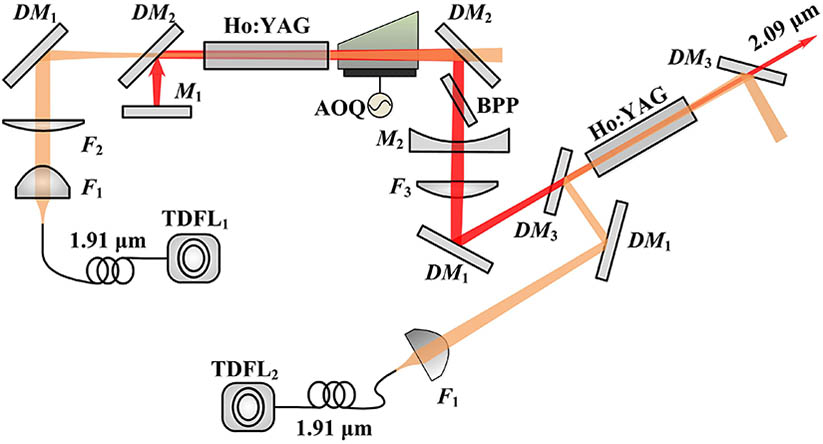
Fig. 1. Layout of the TDFL-pumped Ho:YAG oscillator and amplifier system. (
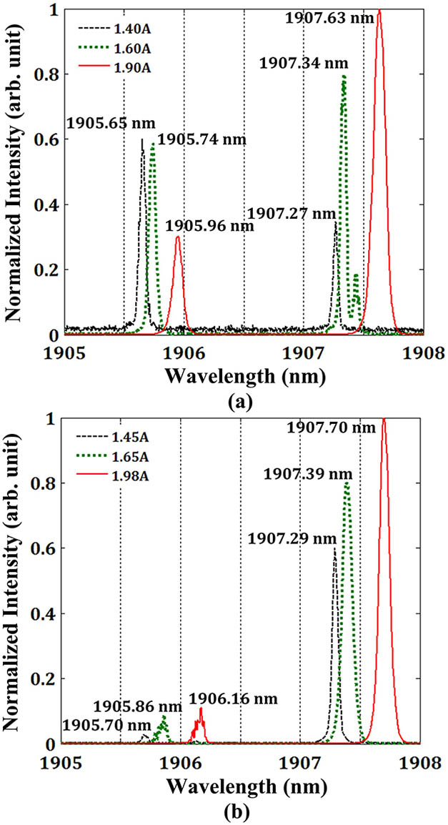
Fig. 2. (Color online) Typical output spectra of
Fig. 3. (Color online) CW output characteristics of polarized the Ho:YAG oscillator. (a) The pump absorption efficiency of the Ho:YAG crystal, the CW output power, and the transmittance of
Fig. 4. (Color online) Pulsed output characteristics of the polarized Ho:YAG oscillator. (a) Pulse energy and pulse duration versus PRF with pump power of 51.6 W; (b) the pulse profiles at eight different PRFs.
Fig. 5. (Color online) Output characteristics of the polarized Ho:YAG amplifier. (a) Amplified output CW power versus pump power from
Fig. 6. Layout of the TDFL-pumped Ho:YAG oscillator and amplifier system. (
Fig. 7. (Color online) (a) Comparison of typical pump pulse profile and parametric pulse profile; (b) the beam quality measurement of parametric light.
Fig. 8. (Color online) (a) Total parametric output average power versus incident pump average power at a PRF of 3 kHz; (b) the beam quality measurements at three typical parametric pulse energies.


Set citation alerts for the article
Please enter your email address

© Copyright 2018-2021 | Chinese Laser Press. All Rights Reserved 沪ICP备15018463号-20