• Laser & Optoelectronics Progress
  • Vol. 56, Issue 4, 040603 (2019)
Xindi Huang1、2, Jia Lu1、2、*, Yang Wang1、2, Jianfei Liu1、2, and Xiangye Zeng1、2
Author Affiliations
  • 1 School of Electronics and Information Engineering, Hebei University of Technology, Tianjin 300401, China
  • 2 Tianjin Key Laboratory of Electronic Materials & Devices, Tianjin 300401, China;
  • show less
    DOI: 10.3788/LOP56.040603 Cite this Article Set citation alerts
    Xindi Huang, Jia Lu, Yang Wang, Jianfei Liu, Xiangye Zeng. Influence of High-Order Sideband on High-Frequency Millimeter Wave System[J]. Laser & Optoelectronics Progress, 2019, 56(4): 040603 Copy Citation Text show less
    Schematic of system. (a) Spectral diagram of the first MZM output; (b) spectral diagram of the second MZM output
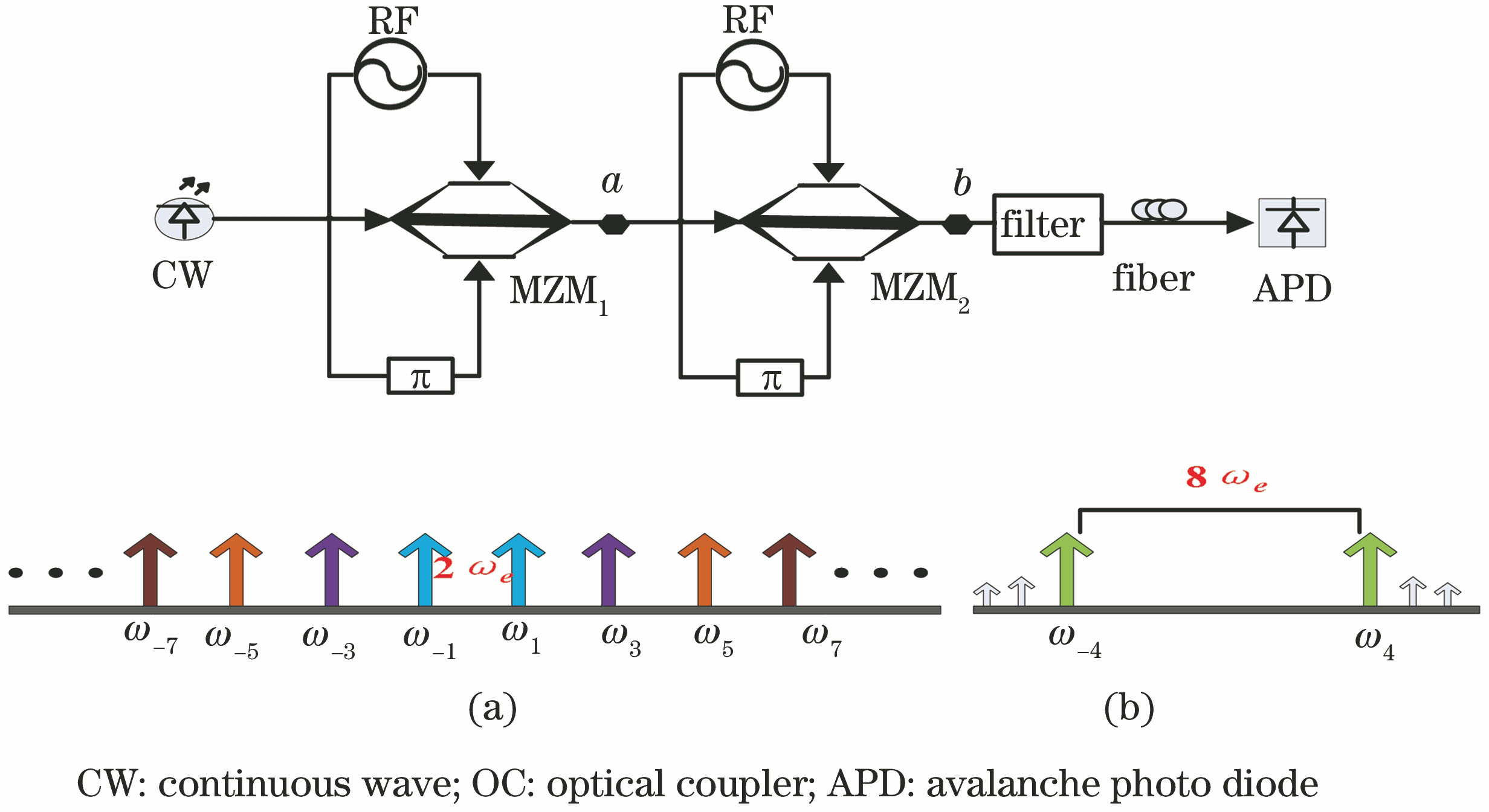
    Fig. 1. Schematic of system. (a) Spectral diagram of the first MZM output; (b) spectral diagram of the second MZM output
    Phase diagram of different sidebands without influence of high-order sideband (ideal condition)
    Fig. 2. Phase diagram of different sidebands without influence of high-order sideband (ideal condition)
    Curves corresponding to different modulation depths. (a) Bessel curve; (b)sideband suppression ratio
    Fig. 3. Curves corresponding to different modulation depths. (a) Bessel curve; (b)sideband suppression ratio
    Sideband phase diagram of MZM2 output. Square height indicates each sideband amplitude and horizontal line position does each sideband phase direction
    Fig. 4. Sideband phase diagram of MZM2 output. Square height indicates each sideband amplitude and horizontal line position does each sideband phase direction
    Phase diagram with consideration of high-order sidebands (actual condition). Square height indicates each sideband amplitude and horizontal line position does each sideband phase direction
    Fig. 5. Phase diagram with consideration of high-order sidebands (actual condition). Square height indicates each sideband amplitude and horizontal line position does each sideband phase direction
    Schematic of carrier wave of first MZM output. (a) Ideal condition; (b) actual condition
    Fig. 6. Schematic of carrier wave of first MZM output. (a) Ideal condition; (b) actual condition
    Generation and reception of millimeter wave. (a) Second-order and fourth-order sidebands under ideal condition; (b) fourth-order and high-order sidebands under actual condition; (c) four-order sideband after filtering; (d) electric spectrum of millimeter wave at 80 GHz
    Fig. 7. Generation and reception of millimeter wave. (a) Second-order and fourth-order sidebands under ideal condition; (b) fourth-order and high-order sidebands under actual condition; (c) four-order sideband after filtering; (d) electric spectrum of millimeter wave at 80 GHz
    BER curves of data at transmission speed of 2.5 Gb/s
    Fig. 8. BER curves of data at transmission speed of 2.5 Gb/s
    FrequencyAmplitudePhase
    ω0t-4ωetE0J3(β1)J1(β2)-3φ1-φ2
    ω0t-2ωetE0J1(β1)J1(β2)-φ1-φ2
    E0J3(β1)J1(β2)-3φ1+φ2
    ω0tE0J1(β1)J1(β2)φ1-φ2
    E0J1(β1)J1(β2)-φ1+φ2
    ω0t+2ωetE0J1(β1)J1(β2)φ1+φ2
    E0J3(β1)J1(β2)3φ1-φ2
    ω0t+4ωetE0J3(β1)J1(β2)3φ1+φ2
    Table 1. Sideband amplitude and phase at same frequency
    Xindi Huang, Jia Lu, Yang Wang, Jianfei Liu, Xiangye Zeng. Influence of High-Order Sideband on High-Frequency Millimeter Wave System[J]. Laser & Optoelectronics Progress, 2019, 56(4): 040603
    Download Citation