• Photonics Research
  • Vol. 8, Issue 7, 1183 (2020)
Dominik Walter Vogt1、2、*, Angus Harvey Jones1、2, Thomas Alan Haase1、2, and Rainer Leonhardt1、2
Author Affiliations
  • 1Department of Physics, The University of Auckland, Auckland 1010, New Zealand
  • 2The Dodd-Walls Centre for Photonic and Quantum Technologies, Dunedin 9016, New Zealand
  • show less
    DOI: 10.1364/PRJ.392288 Cite this Article Set citation alerts
    Dominik Walter Vogt, Angus Harvey Jones, Thomas Alan Haase, Rainer Leonhardt. Subwavelength thick ultrahigh-Q terahertz disc microresonators[J]. Photonics Research, 2020, 8(7): 1183 Copy Citation Text show less
    (a) Schematic illustration of a THz disc resonator with subwavelength thickness. The insert depicts 2 orders of magnitude of the normalized electric field distribution of the fundamental TM mode of a disc resonator with 12 mm diameter and 66.5 μm thickness at 0.6 THz on a logarithmic scale. The HRFZ-Si disc is indicated with the grey solid line. (b) Simulated intrinsic Q factor Q0 for two discs with 6 mm diameter and 72 μm thickness (blue dots) and 12 mm diameter and 66.5 μm thickness (orange dots). The green-shaded area indicates the Q0 of a solid sphere with 6 mm diameter. For simplicity, a constant permittivity corresponding to a material absorption of α=0.006 cm−1 is assumed. (c) Optimal disc thickness (black) and maximal intrinsic Q factor (brown) for diameters from 6 to 60 mm at a design frequency of about 560 GHz. The green-shaded area shows the intrinsic Q factors for solid sphere resonators. (d) FSRs of the disc resonators for diameters from 6 to 60 mm with optimal thicknesses (blue) and solid spheres (green). The solid lines are interpolations of the simulated data points to guide the eye.
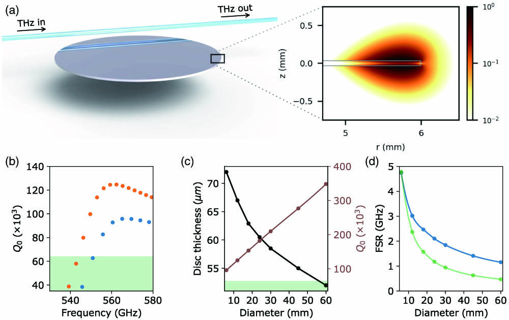
    Fig. 1. (a) Schematic illustration of a THz disc resonator with subwavelength thickness. The insert depicts 2 orders of magnitude of the normalized electric field distribution of the fundamental TM mode of a disc resonator with 12 mm diameter and 66.5 μm thickness at 0.6 THz on a logarithmic scale. The HRFZ-Si disc is indicated with the grey solid line. (b) Simulated intrinsic Q factor Q0 for two discs with 6 mm diameter and 72 μm thickness (blue dots) and 12 mm diameter and 66.5 μm thickness (orange dots). The green-shaded area indicates the Q0 of a solid sphere with 6 mm diameter. For simplicity, a constant permittivity corresponding to a material absorption of α=0.006  cm1 is assumed. (c) Optimal disc thickness (black) and maximal intrinsic Q factor (brown) for diameters from 6 to 60 mm at a design frequency of about 560 GHz. The green-shaded area shows the intrinsic Q factors for solid sphere resonators. (d) FSRs of the disc resonators for diameters from 6 to 60 mm with optimal thicknesses (blue) and solid spheres (green). The solid lines are interpolations of the simulated data points to guide the eye.
    Microscope images of (a) the top and (b) the rim of the 12 mm diameter disc with (66±1) μm thickness. The thin disc resonator is mounted on a 1 mm diameter metallic rod. The different colors in the photograph are due to reflections from various light sources.
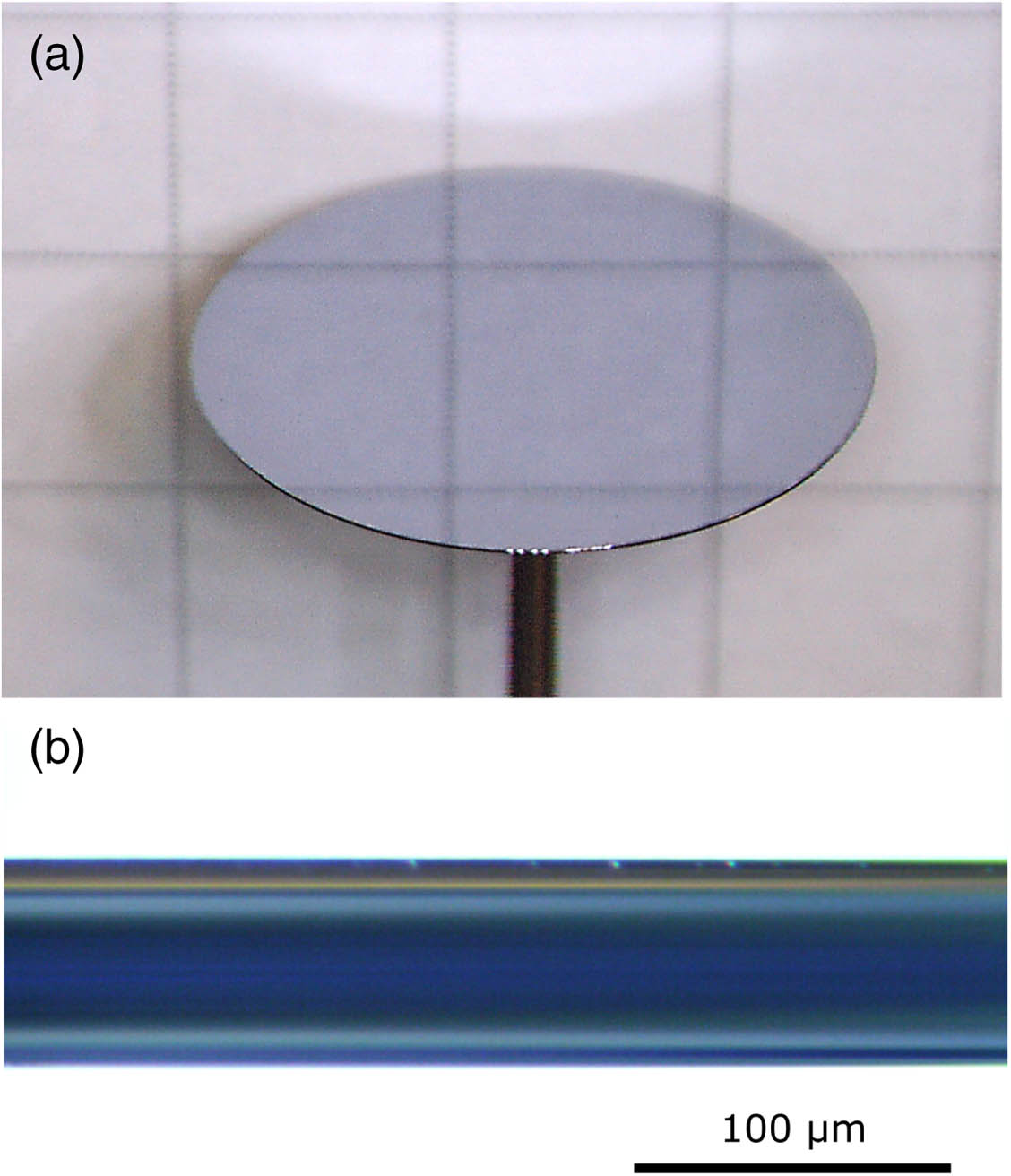
    Fig. 2. Microscope images of (a) the top and (b) the rim of the 12 mm diameter disc with (66±1) μm thickness. The thin disc resonator is mounted on a 1 mm diameter metallic rod. The different colors in the photograph are due to reflections from various light sources.
    Schematic of the experimental setup. The disc resonators are mounted on a 3D computer-controlled translation stage with 0.2 μm precision to accurately control the distance between the waveguide and the resonator. The position of the resonator is monitored using two USB microscopes. The typical resonator–waveguide position for strong coupling is about 200 μm inside the edge of the disc at a height of about 100–200 μm above the disc. The entire setup is placed inside a closed environment with less than 0.02% relative humidity to minimize distortions from water vapor [32].
    Fig. 3. Schematic of the experimental setup. The disc resonators are mounted on a 3D computer-controlled translation stage with 0.2 μm precision to accurately control the distance between the waveguide and the resonator. The position of the resonator is monitored using two USB microscopes. The typical resonator–waveguide position for strong coupling is about 200 μm inside the edge of the disc at a height of about 100–200 μm above the disc. The entire setup is placed inside a closed environment with less than 0.02% relative humidity to minimize distortions from water vapor [32].
    Normalized transmission of the waveguide coupled to (a) the 6 mm disc resonator and (b) the 12 mm disc resonator. Measured (c) normalized transmission and (d) phase profiles (blue) of the resonance at 556 GHz of the 12 mm diameter disc. The corresponding resonance in (b) is highlighted in red. The fit of the analytical model is shown in orange. The frequency step size in subfigures (c) and (d) is 1 MHz.
    Fig. 4. Normalized transmission of the waveguide coupled to (a) the 6 mm disc resonator and (b) the 12 mm disc resonator. Measured (c) normalized transmission and (d) phase profiles (blue) of the resonance at 556 GHz of the 12 mm diameter disc. The corresponding resonance in (b) is highlighted in red. The fit of the analytical model is shown in orange. The frequency step size in subfigures (c) and (d) is 1 MHz.
    Measured intrinsic Q factors of the 6 mm diameter (blue dots) and 12 mm diameter (orange dots) disc resonators in the frequency range from 535 to 600 GHz. The green-shaded area indicates the measured (green dots) material-loss-limited Q0 of a 4 mm diameter HRFZ-Si spherical resonator. The smaller error bars around the water absorption line at 557 GHz are results of more averaged measurements to minimize effects on the Q factor from potential variations in the residual water vapor content in the resonator’s environment. The blue and orange dashed curves indicate the simulated intrinsic Q factors for discs with 6 mm diameter and 70.2 μm thickness and a 12 mm diameter disc with 66.5 μm thickness, respectively. The uncertainty at the absolute resonance frequencies is typically less than 0.5 GHz as indicated with the error bars.
    Fig. 5. Measured intrinsic Q factors of the 6 mm diameter (blue dots) and 12 mm diameter (orange dots) disc resonators in the frequency range from 535 to 600 GHz. The green-shaded area indicates the measured (green dots) material-loss-limited Q0 of a 4 mm diameter HRFZ-Si spherical resonator. The smaller error bars around the water absorption line at 557 GHz are results of more averaged measurements to minimize effects on the Q factor from potential variations in the residual water vapor content in the resonator’s environment. The blue and orange dashed curves indicate the simulated intrinsic Q factors for discs with 6 mm diameter and 70.2 μm thickness and a 12 mm diameter disc with 66.5 μm thickness, respectively. The uncertainty at the absolute resonance frequencies is typically less than 0.5 GHz as indicated with the error bars.
    Dominik Walter Vogt, Angus Harvey Jones, Thomas Alan Haase, Rainer Leonhardt. Subwavelength thick ultrahigh-Q terahertz disc microresonators[J]. Photonics Research, 2020, 8(7): 1183
    Download Citation