Abstract
Artificial structures that exhibit narrow resonance features are key to a myriad of scientific advances and technologies. In particular, exploration of the terahertz (THz) spectrum—the final frontier of the electromagnetic spectrum—would greatly benefit from high-quality resonant structures. Here we present a new paradigm of terahertz silicon disc microresonators with subwavelength thickness. Experimental results utilizing continuous-wave THz spectroscopy establish quality factors in excess of 120,000 at 0.6 THz. Reduction of the disc thickness to a fraction of the wavelength reduces the losses from the silicon substrate and paves the way to unparalleled possibilities for light–matter interaction in the THz frequency range.1. INTRODUCTION
High- microresonators have enabled groundbreaking advances at optical frequencies [1–11]. Their high factors combined with the compact design render the monolithic resonators ideal platforms to drive both fundamental research and technological developments. In particular, microresonators are utilized to understand intriguing quantum phenomena [12] as well as unprecedented nonlinear processes [13], to name but a few. Furthermore, microresonators are harnessed for cutting-edge applications like single-molecule biological sensors [14] and essential buildings blocks for future communication networks [15].
By extension, it has been known for a long time that unlocking the full potential of the terahertz (THz) spectrum calls for the development of high-quality resonant structures at THz frequencies [16]. Consequently, the implementation of such resonators has been a long-standing goal. Yet, despite an ongoing effort, the vast majority of resonant structures feature complicated designs and exhibit significant losses, impeding breakthroughs for future THz technologies [17–19].
It is only recently that the concept of high- monolithic resonators has been transferred to THz frequencies, yielding resonance features more than 2 orders of magnitude narrower compared to previous systems [20]. Despite their recent implementation, the resonators have already been applied for sensing [21] and precision metrology [22], and they have contributed toward the understanding of fundamental aspects of microcavities through a sequence of proof-of-concept experiments [23–26].
Sign up for Photonics Research TOC. Get the latest issue of Photonics Research delivered right to you!Sign up now
Still, the main factor limiting the factor of THz microresonators is the typically strong material absorption of the resonator substrate. The highest- THz resonators reported so far are made of high-resistivity float-zone grown silicon (HRFZ-Si), one of the lowest loss materials known in the THz frequency range [20,27–30]. However, with no significantly better materials in sight, even higher factors are out of reach with typical microresonator designs.
Here we present an experimental demonstration of ultrahigh- THz disc resonators with subwavelength thickness to alleviate the material loss constraint. Unprecedented factors are achieved by thinning the disc resonators to a fraction of the free-space wavelength and therefore minimizing the losses induced by the disc substrate. Also, the disc resonators intrinsically have an extremely large evanescent field that is ideally suited to enhance the interaction between the resonance and its environment. The disc resonators establish a new paradigm of microresonators that are perfectly suited to enhance light–matter interaction, alluding to the possibility of highly sensitive sensors in the THz frequency range.
2. PRINCIPLE AND NUMERICAL ANALYSIS
Figure 1(a) shows a schematic illustration of the THz disc resonators and the employed coupling scheme. A coherent continuous wave (CW) THz signal is coupled to a disc resonator via a single-mode waveguide exciting the THz resonances. A typical electric field distribution of the fundamental TM mode (electric field polarization perpendicular to the surface of the disc) of a disc resonator is depicted in the insert. With a disc thickness of , a large proportion of the field is outside the silicon substrate as a far-reaching evanescent field. The electric field drops to from the surface of the disc within ; for a standard spherical resonator this distance would be about . Please note that, because of the intriguing field distribution, the best coupling is achieved by placing the waveguide above or below the edge of the disc as shown in Fig. 1(a).
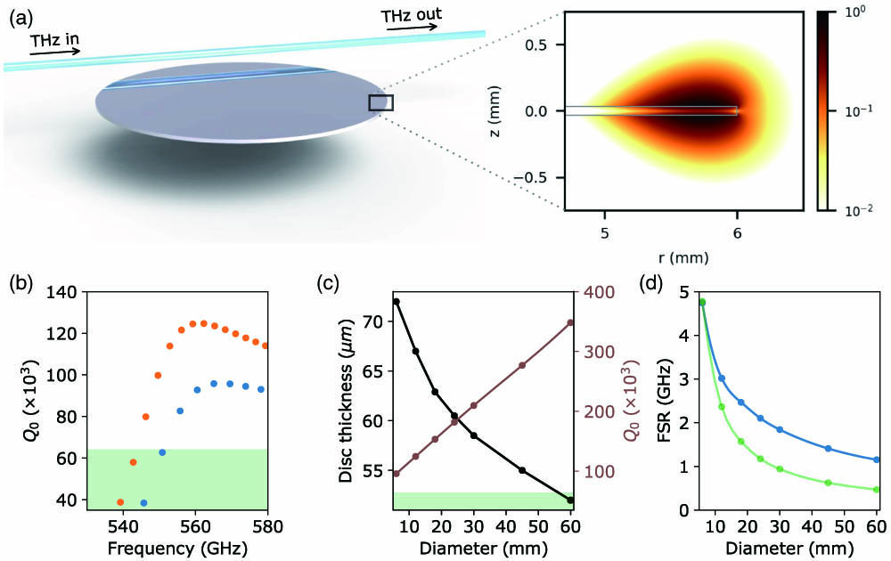
Figure 1.(a) Schematic illustration of a THz disc resonator with subwavelength thickness. The insert depicts 2 orders of magnitude of the normalized electric field distribution of the fundamental TM mode of a disc resonator with 12 mm diameter and 66.5 μm thickness at 0.6 THz on a logarithmic scale. The HRFZ-Si disc is indicated with the grey solid line. (b) Simulated intrinsic factor for two discs with 6 mm diameter and 72 μm thickness (blue dots) and 12 mm diameter and 66.5 μm thickness (orange dots). The green-shaded area indicates the of a solid sphere with 6 mm diameter. For simplicity, a constant permittivity corresponding to a material absorption of is assumed. (c) Optimal disc thickness (black) and maximal intrinsic factor (brown) for diameters from 6 to 60 mm at a design frequency of about 560 GHz. The green-shaded area shows the intrinsic factors for solid sphere resonators. (d) FSRs of the disc resonators for diameters from 6 to 60 mm with optimal thicknesses (blue) and solid spheres (green). The solid lines are interpolations of the simulated data points to guide the eye.
The essence of the resonator design is to reduce the thickness of a disc with a specific diameter until the intrinsic factor is highest at a chosen design frequency. However, once the disc is too thin, the resonance at the design frequency experiences significant radiation losses, similar to bend losses in waveguides, and the intrinsic factor deteriorates rapidly. The characteristic behavior of disc resonators with optimal thickness is clearly visible from the finite-element simulations presented in Fig. 1(b). The blue and orange dotted curves show the intrinsic factors as a function of resonance frequency exemplary for disc resonators with 6 mm diameter/72 μm thickness and 12 mm diameter/66.5 μm thickness, respectively. The shown resonances are separated by one free spectral range (FSR). Starting at 540 GHz, the intrinsic factor increases rapidly until it reaches its maximum value at the design frequency of about 560 GHz. At frequencies above the design frequency, the disc resonators maintain a very high factor over a broad frequency range. This is particularly advantageous for applications where high- resonances are required over a broad frequency range, for example, for multifrequency sensing or broadband precision metrology. The gradual decrease of the intrinsic factor above the design frequency can be understood by the fact that, with increasing frequency (smaller wavelength), the ratio of the wavelength to the disc thickness is decreasing: the resonator modes are more confined to the HRFZ-Si disc and are therefore subject to higher material loss.
Most importantly, the intrinsic factors of the disc resonators with subwavelength thickness are significantly higher compared to the factor of a material-loss-limited resonator design like a solid sphere. This enhancement in factor is nicely visible from the example presented in Fig. 1(b). Here the intrinsic factor of the fundamental mode of a solid sphere is indicated with the green-shaded area to guide the eye: the factors above this area are clearly identified as an improvement compared to the material-loss-limited factor. Please note that in a spherical design the resonance is almost entirely confined to the material, and therefore the factor is inherently limited by the material loss. Also, the same argument would apply, for example, for a disc with a thickness comparable to the wavelength.
As mentioned above, the optimal thickness (highest factor) for the design frequency of a disc with a specific diameter is limited by radiation losses. Once the substrate is too thin, the resonances are no longer fully guided and radiative emission occurs, which is unavoidable in open dielectric resonators [31]. The radiation losses, however, can be reduced by increasing the diameter of the resonator: a smaller radius of curvature directly implies lower radiation losses at the design frequency. Consequently, highest factors can be achieved by simultaneously reducing the disc thickness and increasing the diameter. For example, for the disc with 66.5 μm thickness [orange dotted curve in Fig. 1(b)], the highest factor at a design frequency for 560 GHz is achieved with a diameter of 12 mm. Comparison to the 6 mm diameter disc with 72 μm thickness reveals an increase in factor by 50% to a maximum value of 125,000. In particular, the 12 mm diameter disc has an intrinsic factor of more than twice that of a solid sphere.
Therefore, the intrinsic factor can be further enhanced by using larger but thinner discs. Figure 1(c) demonstrates the optimal disc thickness (black curve) and corresponding highest intrinsic factor (brown curve) as a function of disc diameter from 6 to 60 mm. The simulations are performed for a design frequency of about 560 GHz. For the simulated diameters, a linear behavior is observed with a nearly fourfold increase in the intrinsic factor . Remarkably, at 40 mm diameter, an intrinsic factor in excess of 200,000 is observed. In contrast to the disc resonators, the intrinsic factor of an HRFZ-Si solid sphere does not depend on the diameter as can be seen in the green-shaded area in Fig. 1(c). However, while going to larger diameters significantly enhances the maximum achievable factor of the disc resonators, a practical constraint is given by the fabrication capabilities and required footprint of the resonator. Also, please note that an increase in disc diameter is accompanied with a reduced frequency separation of the resonances, which could be advantageous for broadband or multispecies sensing. Interestingly, the FSRs of the disc resonators with optimal thickness (blue curve) decrease at a lower rate compared to that of solid spheres (green curve) with the same diameters as shown in Fig. 1(d). For example, at a diameter of 30 mm, the FSR of the disc resonator () is twice as large as that of the solid sphere (). This observation is understandable from the fact that the thin disc resonators have a much lower effective refractive index compared to a solid sphere.
Overall, the simulations clearly demonstrate that the concept of THz disc resonators with subwavelength thickness has enormous potential. In particular, factors in excess of 300,000 at 0.6 THz are viable with disc resonators made of HRFZ-Si. In the following, we present the fabrication and experimental characterization of the novel THz microresonators.
3. FABRICATION
The disc resonators are fabricated from 50.8 mm diameter HRFZ-Si wafers with a thickness of 100 μm and a resistivity of using grinding and femtosecond laser micromachining. Initially, the wafers are thinned to the desired thickness by contacting the wafers to an optically flat substrate and subsequent grinding. Continuous monitoring of the thickness using a precision micrometer allows us to achieve the desired thickness with 1 μm accuracy. After decontacting, the raw discs are cut from the wafer using laser micromachining with 220 fs pulses at 800 nm with a repetition rate of 1 kHz and 20 mW power. In the final step, the rim of the raw disc is polished with a fine diamond slurry to remove imperfections caused by the laser micromachining.
Pictures of the top and rim of a 12 mm diameter disc with a thickness of () μm are depicted in Figs. 2(a) and 2(b), respectively. The diamond slurry polishing leads to slightly rounded edges of the discs; however, this and any radial symmetric features do not deteriorate the intrinsic factors of the resonators. Most importantly, the fabrication of the disc resonators is readily applicable to semiconductor industry standards, and therefore much larger and thinner discs, like the 40 mm diameter or 60 mm diameter discs discussed above, can easily be envisioned. In the lab, however, we focus the experimental characterization on two discs with 6 mm and 12 mm diameters, both with design frequencies around 560 GHz.

Figure 2.Microscope images of (a) the top and (b) the rim of the 12 mm diameter disc with () μm thickness. The thin disc resonator is mounted on a 1 mm diameter metallic rod. The different colors in the photograph are due to reflections from various light sources.
4. EXPERIMENTAL CHARACTERIZATION
A. Setup and Methods
The disc resonators are experimentally characterized using coherent CW THz spectroscopy and Hilbert transform for data analysis. A scheme of the experimental setup is shown in Fig. 3. Coherent CW THz radiation is generated and detected using fiber-coupled photoconductive antennas (PCAs) and recorded with a lock-in detection technique (Toptica TeraScan 1550 nm [33]). The smallest frequency step size of the system is 1 MHz. The linearly polarized THz radiation is collimated and focused using specially developed symmetric-pass polymer lenses [34]. With a focal spot size of , the 25 mm focal length lenses (numerical aperture is 0.7) are perfectly suited to efficiently couple to the waveguide that is used to excite the THz disc resonators. The design of the waveguide is essential to achieve phase matching with the investigated HRFZ-Si disc resonators. Here we are using an air–Tefzel–silica step-index waveguide with a 200 μm core diameter made of low OH-content silica, surrounded by a 13 μm thick layer of Tefzel fluoroplastic resin. The refractive indices of the silica core and the fluoroplastic resin are about 1.96 and 1.5, respectively, at 0.6 THz [35]. The waveguide provides single-mode operation in the frequency range from 0.4 to 0.65 THz with an effective refractive index of 1.27 to 1.37 from 540 to 600 GHz. Intriguingly, phase matching to the HRFZ-Si discs can be readily achieved with the air–Tefzel–silica step-index waveguide despite the large material refractive index of the silicon substrate of at 0.6 THz [22]. Since a substantial part of the resonances is guided outside the high-refractive-index material of the disc with subwavelength thickness, the effective refractive index of the resonator mode is much lower than the material refractive index. For example, the phase refractive index for the fundamental mode of a 12 mm diameter disc with 66.5 μm thickness increases from 1.20 to 1.34 in the region from 540 to 600 GHz, resulting in nearly perfect phase matching with the air–Tefzel–silica waveguide. Please note that the same waveguide can be used to couple to all the different resonators considered in this study.
Figure 3.Schematic of the experimental setup. The disc resonators are mounted on a 3D computer-controlled translation stage with 0.2 μm precision to accurately control the distance between the waveguide and the resonator. The position of the resonator is monitored using two USB microscopes. The typical resonator–waveguide position for strong coupling is about 200 μm inside the edge of the disc at a height of about 100–200 μm above the disc. The entire setup is placed inside a closed environment with less than 0.02% relative humidity to minimize distortions from water vapor [32].
The excited resonances are characterized by normalizing the signal transmitted from the waveguide coupled to the resonator (sample scan) to the transmitted signal without coupling to the resonator (reference scan). Normalizing the sample scan to an appropriate reference scan eliminates effects like the frequency-dependent performance of the PCAs and standing waves present in the setup. The recorded scans are analyzed using the Hilbert transform, which provides great advantages in data processing for coherent CW THz spectroscopy. In particular, the Hilbert transform provides a frequency resolution that is only limited by the linewidth of the lasers used to generate and detect the THz radiation [36]. The intricacies of the employed data analysis using Hilbert transform are explained in great detail elsewhere [37].
B. Results
Figures 4(a) and 4(b) show the normalized transmission of the waveguide coupled to the 6 mm and 12 mm diameter disc resonators, respectively, exemplary in the frequency range from 550 to 580 GHz. Comparison of the measured FSRs and factors with simulations clearly identifies the strongest excited resonances in Figs. 4(a) and 4(b) as the fundamental TM modes of the disc resonators. In particular, the fundamental TM modes show explicitly higher factors compared to higher-order radial modes. Also, the expected decrease in FSR for the 12 mm diameter disc compared to the 6 mm diameter disc is clearly visible.
Figure 4.Normalized transmission of the waveguide coupled to (a) the 6 mm disc resonator and (b) the 12 mm disc resonator. Measured (c) normalized transmission and (d) phase profiles (blue) of the resonance at 556 GHz of the 12 mm diameter disc. The corresponding resonance in (b) is highlighted in red. The fit of the analytical model is shown in orange. The frequency step size in subfigures (c) and (d) is 1 MHz.
In the following, the disc resonators are characterized by analyzing the intrinsic factors of the fundamental modes. This allows us to fully characterize the performance of the disc resonators around the design frequency, similar to the numerical simulations discussed above. The intrinsic factors are extracted from the measurements by fitting the measured normalized transmission and phase profiles simultaneously with the analytic equation describing coupling of a waveguide to a microresonator [38]. Figures 4(c) and 4(d) show the measured normalized transmission and phase profiles, respectively, exemplary for the fundamental mode at 556 GHz of the 12 mm diameter disc resonator. The fit of the analytic model (orange) is in very good agreement with the measurements; the intrinsic factor of this mode is 121,000.
Figure 5 summarizes the measured intrinsic factors for the 6 mm (blue dots) and 12 mm (orange dots) diameter disc resonators. The uncertainty in is typically less than 5% as shown with the error bars in Fig. 5; smaller uncertainties can be achieved by increasing the measurement time. The green dots show the measured intrinsic factors for a 4 mm diameter HRFZ-Si solid sphere for some selected resonances. The spherical resonator has optical surface quality and shows unnoticeable deviations from a perfect sphere [20]. The spherical resonator is consequently an excellent reference, as the intrinsic factor is solely limited by the material loss of the HRFZ-Si and not by fabrication imperfections. Please note that in the experiment the same waveguide is used to couple to the disc resonators and spherical resonator, and consequently only higher-order radial modes are excited in the spherical resonator [20]. However, comparison with finite-element simulations clearly shows that the factor of these higher-order radial modes is not limited by radiation losses.
Figure 5.Measured intrinsic factors of the 6 mm diameter (blue dots) and 12 mm diameter (orange dots) disc resonators in the frequency range from 535 to 600 GHz. The green-shaded area indicates the measured (green dots) material-loss-limited of a 4 mm diameter HRFZ-Si spherical resonator. The smaller error bars around the water absorption line at 557 GHz are results of more averaged measurements to minimize effects on the factor from potential variations in the residual water vapor content in the resonator’s environment. The blue and orange dashed curves indicate the simulated intrinsic factors for discs with 6 mm diameter and 70.2 μm thickness and a 12 mm diameter disc with 66.5 μm thickness, respectively. The uncertainty at the absolute resonance frequencies is typically less than 0.5 GHz as indicated with the error bars.
The measurements for the disc resonators follow to a high degree the trend predicted by the numerical analysis. To guide the eye, the blue and orange dashed curves indicate the simulated intrinsic factors for discs with 6 mm diameter and 70.2 μm thickness and a 12 mm diameter disc with 66.5 μm thickness, respectively. Also, the corresponding simulated intrinsic factor of a 4 mm diameter HRFZ-Si solid sphere is indicated with the green-shaded area under the green dashed curve. As the frequency is increased, first the intrinsic factor increases rapidly and then there is a slow decrease—exactly as predicted by the simulations. Also, the measured increase in intrinsic factor by doubling the disc diameter is in very good agreement with the simulations. The observed minor deviations from the simulations are most likely caused by slight imperfections in the resonator geometry that are not considered in the simulations. Also, the simulations do not consider a frequency-dependent material loss of the silicon substrate. Most importantly, however, both disc resonators have a substantially higher factor compared to the solid sphere. In particular, the 12 mm diameter disc has an intrinsic factor of more than 120,000 at about 560 GHz. To the best of our knowledge, this is the highest factor ever reported for a monolithic resonator in the THz frequency range.
5. CONCLUSION
The presented results pioneer a novel concept of THz resonators. Numerical as well as experimental investigations establish that the subwavelength thick disc resonators alleviate the constraint of strong material loss and therefore overcome the main obstacle impeding the breakthrough of ultrahigh- THz microresonators. In particular, measurements with coherent CW THz spectroscopy reveal unprecedented factors in excess of 120,000 at 0.6 THz. Moreover, the excellent agreement between measurements and simulations provides strong indication that factors in excess of 300,000 in the THz frequency range are within reach if larger resonators are implemented. We envision that disc resonators with subwavelength thickness will contribute an essential part to the exploration of the final frontier of the electromagnetic spectrum.
References
[1] K. J. Vahala. Optical microcavities. Nature, 424, 839-846(2003).
[2] T. Herr, V. Brasch, J. D. Jost, C. Y. Wang, N. M. Kondratiev, M. L. Gorodetsky, T. J. Kippenberg. Temporal solitons in optical microresonators. Nat. Photonics, 8, 145-152(2014).
[3] A. L. Gaeta, M. Lipson, T. J. Kippenberg. Photonic-chip-based frequency combs. Nat. Photonics, 13, 158-169(2019).
[4] A. Rueda, F. Sedlmeir, M. Kumari, G. Leuchs, H. G. Schwefel. Resonant electro-optic frequency comb. Nature, 568, 378-381(2019).
[5] T. Herr, K. Hartinger, J. Riemensberger, C. Wang, E. Gavartin, R. Holzwarth, M. Gorodetsky, T. Kippenberg. Universal formation dynamics and noise of Kerr-frequency combs in microresonators. Nat. Photonics, 6, 480-487(2012).
[6] P. Del’Haye, A. Schliesser, O. Arcizet, T. Wilken, R. Holzwarth, T. J. Kippenberg. Optical frequency comb generation from a monolithic microresonator. Nature, 450, 1214-1217(2007).
[7] D. Armani, T. Kippenberg, S. Spillane, K. Vahala. Ultra-high-Q toroid microcavity on a chip. Nature, 421, 925-928(2003).
[8] M.-G. Suh, Q.-F. Yang, K. Y. Yang, X. Yi, K. J. Vahala. Microresonator soliton dual-comb spectroscopy. Science, 354, 600-603(2016).
[9] P. Marin-Palomo, J. N. Kemal, M. Karpov, A. Kordts, J. Pfeifle, M. H. Pfeiffer, P. Trocha, S. Wolf, V. Brasch, M. H. Anderson, R. Rosenberger, K. Vijayan, W. Freude, T. J. Kippenberg, C. Koos. Microresonator-based solitons for massively parallel coherent optical communications. Nature, 546, 274-279(2017).
[10] D. V. Strekalov, C. Marquardt, A. B. Matsko, H. G. Schwefel, G. Leuchs. Nonlinear and quantum optics with whispering gallery resonators. J. Opt., 18, 123002(2016).
[11] T. J. Kippenberg, A. L. Gaeta, M. Lipson, M. L. Gorodetsky. Dissipative Kerr solitons in optical microresonators. Science, 361, eaan8083(2018).
[12] S. Spillane, T. Kippenberg, K. Vahala, K. Goh, E. Wilcut, H. Kimble. Ultrahigh-Q toroidal microresonators for cavity quantum electrodynamics. Phys. Rev. A, 71, 013817(2005).
[13] N. L. B. Sayson, T. Bi, V. Ng, H. Pham, L. S. Trainor, H. G. Schwefel, S. Coen, M. Erkintalo, S. G. Murdoch. Octave-spanning tunable parametric oscillation in crystalline Kerr microresonators. Nat. Photonics, 13, 701-706(2019).
[14] F. Vollmer, S. Arnold. Whispering-gallery-mode biosensing: label-free detection down to single molecules. Nat. Methods, 5, 591-596(2008).
[15] J. Pfeifle, V. Brasch, M. Lauermann, Y. Yu, D. Wegner, T. Herr, K. Hartinger, P. Schindler, J. Li, D. Hillerkuss, R. Schmogrow, C. Weimann, R. Holzwarth, W. Freude, J. Leuthold, T. J. Kippenberg, C. Koos. Coherent terabit communications with microresonator Kerr frequency combs. Nat. Photonics, 8, 375-380(2014).
[16] M. Tonouchi. Cutting-edge terahertz technology. Nat. Photonics, 1, 97-105(2007).
[17] S. S. Harsha, N. Laman, D. Grischkowsky. High-Q terahertz Bragg resonances within a metal parallel plate waveguide. Appl. Phys. Lett., 94, 091118(2009).
[18] C. M. Yee, M. S. Sherwin. High-Q terahertz microcavities in silicon photonic crystal slabs. Appl. Phys. Lett., 94, 154104(2009).
[19] W. Cao, R. Singh, I. A. Al-Naib, M. He, A. J. Taylor, W. Zhang. Low-loss ultra-high-Q dark mode plasmonic Fano metamaterials. Opt. Lett., 37, 3366-3368(2012).
[20] D. W. Vogt, R. Leonhardt. Ultra-high Q terahertz whispering-gallery modes in a silicon resonator. APL Photon., 3, 051702(2018).
[21] C. Mathai, R. Jain, V. Achanta, S. Duttagupta, D. Ghindani, N. Joshi, R. Pinto, S. Prabhu. Sensing at terahertz frequency domain using a sapphire whispering gallery mode resonator. Opt. Lett., 43, 5383-5386(2018).
[22] D. W. Vogt, A. H. Jones, R. Leonhardt. Thermal tuning of silicon terahertz whispering-gallery mode resonators. Appl. Phys. Lett., 113, 011101(2018).
[23] J. Zhang, D. Grischkowsky. Whispering-gallery-mode cavity for terahertz pulses. J. Opt. Soc. Am. B, 20, 1894-1904(2003).
[24] D. W. Vogt, A. H. Jones, H. G. Schwefel, R. Leonhardt. Anomalous blue-shift of terahertz whispering-gallery modes via dielectric and metallic tuning. Opt. Lett., 44, 1319-1322(2019).
[25] D. W. Vogt, A. H. Jones, R. Leonhardt. Free-space coupling to symmetric high-Q terahertz whispering-gallery mode resonators. Opt. Lett., 44, 2220-2223(2019).
[26] D. W. Vogt, R. Leonhardt. Fano resonances in a high-Q terahertz whispering-gallery mode resonator coupled to a multi-mode waveguide. Opt. Lett., 42, 4359-4362(2017).
[27] G. Annino, M. Cassettari, I. Longo, M. Martinelli. Whispering gallery modes in a dielectric resonator: characterization at millimeter wavelength. IEEE Trans. Microw. Theory Tech., 45, 2025-2034(1997).
[28] S. Preu, H. Schwefel, S. Malzer, G. Döhler, L. Wang, M. Hanson, J. Zimmerman, A. Gossard. Coupled whispering gallery mode resonators in the terahertz frequency range. Opt. Express, 16, 7336-7343(2008).
[29] S. Preu, S. I. Schmid, F. Sedlmeir, J. Evers, H. G. Schwefel. Directional emission of dielectric disks with a finite scatterer in the THz regime. Opt. Express, 21, 16370-16380(2013).
[30] Z. Wang, S. Yuan, G. Dong, R. Wang, L. Chen, X. Wu, X. Zhang. On-chip single-mode high-Q terahertz whispering gallery mode resonator. Opt. Lett., 44, 2835-2838(2019).
[31] A. B. Matsko, V. S. Ilchenko. Optical resonators with whispering gallery modes I: basics. IEEE J. Sel. Top. Quantum Electron., 12, 3-14(2006).
[32] M. Van Exter, C. Fattinger, D. Grischkowsky. Terahertz time-domain spectroscopy of water vapor. Opt. Lett., 14, 1128-1130(1989).
[33] A. J. Deninger, A. Roggenbuck, S. Schindler, S. Preu. 2.75 THz tuning with a triple-DFB laser system at 1550 nm and InGaAs photomixers. J. Infrared Millimeter Terahertz Waves, 36, 269-277(2015).
[34] Y. H. Lo, R. Leonhardt. Aspheric lenses for terahertz imaging. Opt. Express, 16, 15991-15998(2008).
[35] S. Tsuzuki, N. Kuzuu, H. Horikoshi, K. Saito, K. Yamamoto, M. Tani. Influence of OH-group concentration on optical properties of silica glass in terahertz frequency region. Appl. Phys. Express, 8, 072402(2015).
[36] D. W. Vogt, R. Leonhardt. High resolution terahertz spectroscopy of a whispering gallery mode bubble resonator using Hilbert analysis. Opt. Express, 25, 16860-16866(2017).
[37] D. W. Vogt, M. Erkintalo, R. Leonhardt. Coherent continuous wave terahertz spectroscopy using Hilbert transform. J. Infrared Millimeter Terahertz Waves, 40, 524-534(2019).
[38] M. L. Gorodetsky, V. S. Ilchenko. Optical microsphere resonators: optimal coupling to high-Q whispering-gallery modes. J. Opt. Soc. Am. B, 16, 147-154(1999).


