
Yize Liang, Chengkun Cai, Kangrui Wang, Xiaokang Lian, Jue Wang, Jinfeng Liu, Lei Shen, Jian Wang, "Low-insertion-loss femtosecond laser-inscribed three-dimensional high-density mux/demux devices," Adv. Photon. Nexus 2, 036002 (2023)
- Advanced Photonics Nexus
- Vol. 2, Issue 3, 036002 (2023)
Abstract
1 Introduction
Over the last couple of years, the communication capacity of single-mode fiber (SMF)-based systems has been rapidly pushed toward its theoretical limit1 due to the explosive growth in demand for optical communication traffic. Thus, space-division multiplexing (SDM) has been proposed and demonstrated to be a promising technology to further increase the capacity of a single optical fiber.2,3 There are currently two kinds of fiber-based SDM communication systems. One propagates orthogonal spatial modes loaded with different signals in the single core of a multimode fiber4
One important component for such an MCF-based SDM system is a fan-in/fan-out (FIFO) device with broad bandwidth, low insertion loss, and low crosstalk, which acts as an SDM mux/demux device. With the development of MCF-based SDM technology, several kinds of FIFO devices have been proposed and fabricated. Generally speaking, they can be divided into three kinds: traditional free-space FIFO couplers,16,17 fiber-based FIFO couplers,18
In this work, we design and fabricate 19-channel FIFO devices based on femtosecond laser direct writing. The insertion losses of 19 channels are evaluated to be no more than 1.2 dB at 1550 nm with an average value of 0.88 dB. In addition, insertion losses of specific channels are characterized to be almost the same over the whole C+L band, proving the broad bandwidth of this FIFO device. Intercore crosstalk of the FIFO device is also evaluated to be no more than
Sign up for Advanced Photonics Nexus TOC. Get the latest issue of Advanced Photonics Nexus delivered right to you!Sign up now
2 Results
2.1 Design and Fabrication of the FIFO Device
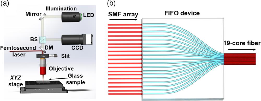
Figure 1(a) displays the schematic of the femtosecond laser direct writing system. The glass sample (
![]()
Figure 1.(a) Schematic of the femtosecond laser direct writing system and (b) concept of the femtosecond laser-inscribed device. BS, beam splitter; DM, dichroic mirror; CCD, charge-coupled device.
For traditional ultrafast laser-inscribed FIFO devices fabricated in quartz glass, they are usually fabricated in the thermal fabrication regime (e.g., 5.1-MHz ultrafast laser). In such regimes, cumulative effects take place. The low pulse energy of the applied high-frequency lasers requires a high NA objective lens to achieve a few-hundred micrometers’ vertical fabrication range. In these regimes, modifications are of a circular cross section due to the isotropic heat diffusion. In contrast, we choose a low-frequency (100 kHz) laser to accomplish the material modification produced by the individual pulses. The applied low NA objective lens enables the vertical fabrication range up to a few micrometers. Thus, waveguides inscribed in low-frequency regimes usually exhibit significant loss and strong core asymmetry with a large aspect ratio. However, we apply the slit beam shaping technique to fabricate waveguides with a circular cross section and low loss over a large depth range. In addition, the main parameters of the fabrication process are scanned, and the comprehensive optimal value is selected. In this way, we achieve both the ultralow propagation loss (
The concept of a fabricated 19-channel FIFO device is indicated in Fig. 1(b). A side-by-side 19-channel Gaussian beam array that outputs from a SMF array is incident into the FIFO device. As a result, different beams of the beam array are confined to transmit along different channels in the FIFO device. The transmission of different beams in their corresponding channels is, in other words, a process of beam array redistribution in three dimensions. The redistributed beam array forms a distribution that matches a 19-core fiber. Therefore, light beams output from a SMF array can be accurately coupled into diverse cores of a 19-core fiber, as displayed in Fig. 1(b). By modulating different signals onto different beams transmitting in the SMF array, such a 19-channel FIFO device can be used as an SDM multiplexer that connects a commercial SMF array and a 19-core fiber.
Figure 2(a) shows the designed end facets of the input and output of the 19-channel FIFO device, while Fig. 2(b) shows the captured output end facet by applying a microscope. The side-by-side channel distribution at the input of the FIFO device possesses a channel spacing of
![]()
Figure 2.(a) Design of the input end facet and output end facet of the FIFO device; (b) captured output end facet of the FIFO device; (c) captured cross section of applied 19-core fiber; and (d) design of the 2D track of the waveguide.
The fundamental principle for fabricating such a 19-channel FIFO device relies on the direct writing of 19 waveguides in glass. The 19 waveguides inside the FIFO device get closer to each other along the track from its input to output, as indicated in Fig. 1(b). In what follows, we explain the design of the FIFO device in detail.
First, the design of the input and output channel distribution of the 19-channel FIFO device is required. The channel spacing of the input end of FIFO device is set to be
After finishing the design of the input and output channel distributions of the 19-channel FIFO device, tracks of the 19 waveguides inside the FIFO device should be determined, with the principle of independent transmission. Ultraviolet (UV) optical quartz glass with a size of
2.2 Experimental Setup of 19-Channel FIFO System
To achieve the characterization of the 19-channel FIFO device, we use a pair of 19-channel FIFO devices to establish a 19-channel FIFO system. The schematic of the 19-channel FIFO system is shown in Fig. 3(a). A C+L band tunable laser is connected to an optical coupler (OC) so that light beam output from the laser is split into 19 beams transmitting in an SMF array. The 19-channel fiber-guided beams then output from the SMF array and enter the FIFO device. During the transmission in the FIFO device, the 19-channel beam array is redistributed to form a distribution that matches the 19-core fiber. Then the 19-channel beam array is coupled into a 1-km 19-core fiber. The applied 19-core fiber possesses a measured transmission loss of 0.26 dB/km. To demultiplex the 19-channel beams output from the 1-km 19-core fiber, another FIFO device is reversely inserted into the experimental setup, as shown in Fig. 3(a). Finally, the demultiplexed side-by-side 19-channel beams that output from the FIFO device are incident into another SMF array, thereby demultiplexing the 19-channel beams into 19 different SMF channels.
![]()
Figure 3.(a) Experimental setup of the 19-channel FIFO system based on a pair of FIFO devices; (b) 1-km 19-core fiber; (c) 19-channel FIFO device; (d) SMF array. OC, optical coupler.
In the experiment, all the coupling processes are monitored in real time by a visible CCD. To accomplish accurate coupling alignment, the two SMF arrays and the 1-km 19-core fiber are placed on six-axes stages, which enable precise control of three-dimensional angles and displacements. In addition, two rotational fiber holders are utilized to rotate the two ports of the 19-core fiber to finish the channel distribution match between the 19-core fiber and the FIFO devices. Once the 19-channel FIFO system is successfully established, all the devices (i.e., the two SMF arrays, the two FIFO devices, and the 1-km 19-core fiber) can be integrated by applying a UV glue so that the applied six-axes stages, rotational fiber holders, and monitoring CCD are freed.
2.3 Characterization of the FIFO Device
To obtain the performance of the fabricated 19-channel FIFO device, a comprehensive characterization is carried out, including capturing the output light field, measuring the insertion loss, characterizing the bandwidth, and evaluating the crosstalk of the 19-channel FIFO device.
The intensity profile of the output light field of the 19-channel FIFO device is displayed in Fig. 4(a). It is captured after the FIFO device output by using a
![]()
Figure 4.Intensity profiles of the output light fields of (a) 19-channel FIFO device and (b) 1-km 19-core fiber.
The insertion losses of a FIFO device result in lower received power of an SDM communication system, thereby affecting the bit error rate (BER) performance of the SDM communication system. Here, we evaluate the insertion losses of 19 different channels of the FIFO device at 1550 nm. Light beams output from the FIFO device are coupled into a short SMF for insertion loss characterization. During the loss characterizations, the input power only exists in the channel that is under test. First, the input intensity of a specific channel is measured by recording its power at the output of the OC using a fiber power meter. Then, the output intensity of this channel is measured at the output of the SMF by applying the same fiber power meter. Finally, the insertion losses of the 19 different channels are calculated by means of subtracting the input intensities from their output intensities. The measured insertion losses of 19 different channels are evaluated to be no more than 1.2 dB at 1550 nm, which can be found in Fig. 5(a). It is worth mentioning that the measured insertion losses contain coupling losses and linear propagation loss of the FIFO waveguide. Thus, a coupling loss about 0.3 dB/facet and a linear propagation loss of about 0.1 dB/cm are evaluated for channel 10 at 1550 nm. Central channels feature lower insertion losses due to their lower bending losses and shorter paths. Compared to central channels, the low increase of channel path length of the farthest channel will not affect the insertion loss as much, due to the linear propagation loss of
![]()
Figure 5.(a) Measured insertion losses of 19 different channels of the FIFO device at 1550 nm and (b) evaluated insertion losses of channels 10, 14, and 19 from 1528 to 1625 nm.
The wavelength-division multiplexing (WDM) technology is an efficient approach to improve the optical communication capacity. Hence, the bandwidth of an SDM FIFO device is required to be large enough so that the SDM technology can be used together with WDM to further increase the capacity of the optical network. Fortunately, the fabricated 19-channel FIFO device on a glass chip has the advantage of broad bandwidth. Therefore, we measure the insertion losses of three different channels (central channel, channel 10; farther channel, channel 14; the farthest channel, channel 19) over the whole C+L band to prove it. Insertion losses of these three different channels are evaluated at diverse wavelengths from 1528 to 1625 nm with a measurement interval of 1 nm, as illustrated in Fig. 5(b). Insertion losses at different wavelengths almost retain the same value, demonstrating the C+L bandwidth of the fabricated FIFO device. Thus, the femtosecond laser-inscribed 19-channel FIFO device can be utilized as a (de)multiplexer in wavelength-space division multiplexing (WSDM) applications.
The interchannel crosstalk of an SDM system describes how much power in the input channel couples to other channels. In addition to insertion losses, the interchannel crosstalk is another factor that determines the performance of an SDM communication system. The interchannel crosstalk can be evaluated by measuring the output power of the input channel and the output power of other channels. Here, we characterize the intercore crosstalk of the 19-channel FIFO device (for details about the crosstalk characterization, refer to Fig. S1, Fig. S2, and Table S2 in the Supplemental Material). For a specific channel, we choose the biggest crosstalk between it and other channels as the crosstalk of this channel, as shown in Fig. 6. All the channels possess crosstalk of no more than
![]()
Figure 6.Measured crosstalk of 19 different channels to other channels.
3 Conclusion and Discussion
We designed and fabricated a 19-channel FIFO waveguide based on femtosecond laser direct writing. The insertion losses of 19 channels are evaluated to be no more than 1.2 dB at 1550 nm, with an average value of 0.88 dB. Intercore crosstalk of the FIFO device is also evaluated to be no more than
Compared to free-space FIFO solutions16,17 and fiber-based solutions,18,19 our FIFO mux/demux devices have the advantages of small size and low cost. In contrast to on-chip FIFO solutions based on other material platforms,22
Yize Liang received his BS degree from Huazhong University of Science and Technology in 2018. Currently, he is pursuing his PhD at Wuhan National Laboratory for Optoelectronics and School of Optical and Electronic Information at Huazhong University of Science and Technology. His research interests include structured light and multimode fibers.
Chengkun Cai received his BS degree from Huazhong University of Science and Technology in 2017. Currently, he is pursuing his PhD at Wuhan National Laboratory for Optoelectronics and School of Optical and Electronic Information at Huazhong University of Science and Technology. His research interest includes femtosecond laser fabrication.
Kangrui Wang received his BS degree from Huazhong University of Science and Technology in 2022. Currently, he is pursuing his PhD at Wuhan National Laboratory for Optoelectronics and School of Optical and Electronic Information at Huazhong University of Science and Technology. His research interest includes femotosecond laser direct writing.
Xiaokang Lian received his PhD in optical engineering from Technological University Dublin, Dublin, Ireland, in 2021. Currently, he is working as a postdoctoral research associate in Multi-Dimensional Photonics Laboratory at the Wuhan National Laboratory for Optoelectronics, Huazhong University of Science and Technology, Wuhan, China.
Jue Wang is pursuing his PhD at Wuhan National Laboratory for Optoelectronics and School of Optical and Electronic Information at Huazhong University of Science and Technology. His research interests include femtosecond laser micron-nano fabrication and optical devices.
Jinfeng Liu received his BS degree from Huazhong University of Science and Technology in 2022. Currently, he is pursuing his PhD at Wuhan National Laboratory for Optoelectronics at Huazhong University of Science and Technology. His research interest includes light field manipulation.
Lei Shen received his PhD in experimental mechanics from Huazhong University of Science and Technology. Currently, he is working as a senior specialist of Yangtze Optical Fiber and Cable Joint Stock Limited Company, Wuhan, Hubei province. His research interests include the design, fabrication, and measurement of new optical fiber and cable products for outside plant, indoor, and FTTH applications.
Jian Wang received his PhD in physical electronics from Wuhan National Laboratory for Optoelectronics, Huazhong University of Science and Technology, Wuhan, China, in 2008. He worked as a postdoctoral research associate in the Optical Communications Laboratory, University of Southern California, Los Angeles, California, United States, from 2009 to 2011. Currently, he is working as a professor at Wuhan National Laboratory for Optoelectronics, Huazhong University of Science and Technology. He is the vice director of Wuhan National Laboratory for Optoelectronics, Huazhong University of Science and Technology. He leads the Multi-Dimensional Photonics Laboratory. His research interests include optical communications, optical signal processing, silicon photonics, photonic integration, orbital angular momentum, and structured light. He has published more than 260 refereed international journal papers in Science, Science Advances, Nature Photonics, Nature Communications, Light: Science and Applications, Physical Review Letters, Optica, Laser and Photonics Reviews, Research, PhotoniX, Advanced Photonics, ACS Photonics, etc. He has authored and co-authored more than 150 international conference papers on OFC, ECOC, CLEO, etc. He has also given more than 110 tutorial/keynote/invited talks at international conferences including an invited talk at OFC2014 and tutorial talk at OFC2016. He is currently an OPTICA Fellow and SPIE Fellow.
References
[5] J. Wang. Advances in communications using optical vortices. Photonics Res., 4, B14-B28(2016).
[8] J. Sakaguchi et al. 19-core fiber transmission of 19× 100× 172-Gb/s SDM-WDM-PDM-QPSK signals at 305Tb/s, PDP5C.1.
[10] B. J. Puttnam et al. 2.15 Pb/s transmission using a 22 core homogeneous single-mode multi-core fiber and wideband optical comb(2015).
[12] G. Rademacher et al. 10.66 peta-bit/s transmission over a 38-core-three-mode fiber, Th3H.1.
[13] D. Soma et al. 50.47-Tbit/s Standard cladding ultra-low-loss coupled 4-Core fiber transmission over 9,150 km, W7D.3.
[18] L. Gan et al. Ultra-low crosstalk fused taper type fan-in/fan-out devices for multicore fibers, Th3D.3.
[43] P. Mitchell et al. 57 channel (19× 3) spatial multiplexer fabricated using direct laser inscription, M3K.5.
[44] S. Rommel et al. Characterization of a fiber-coupled 36-core 3-mode photonic lantern spatial multiplexer, NeW3B. 2.


Set citation alerts for the article
Please enter your email address

© Copyright 2018-2021 | Chinese Laser Press. All Rights Reserved 沪ICP备15018463号-20