
S. Eliezer, J. M. Martinez-Val, Z. Henis, N. Nissim, S. V. Pinhasi, A. Ravid, M. Werdiger, E. Raicher. Physics and applications with laser-induced relativistic shock waves[J]. High Power Laser Science and Engineering, 2016, 4(3): 03000e25
- High Power Laser Science and Engineering
- Vol. 4, Issue 3, 03000e25 (2016)
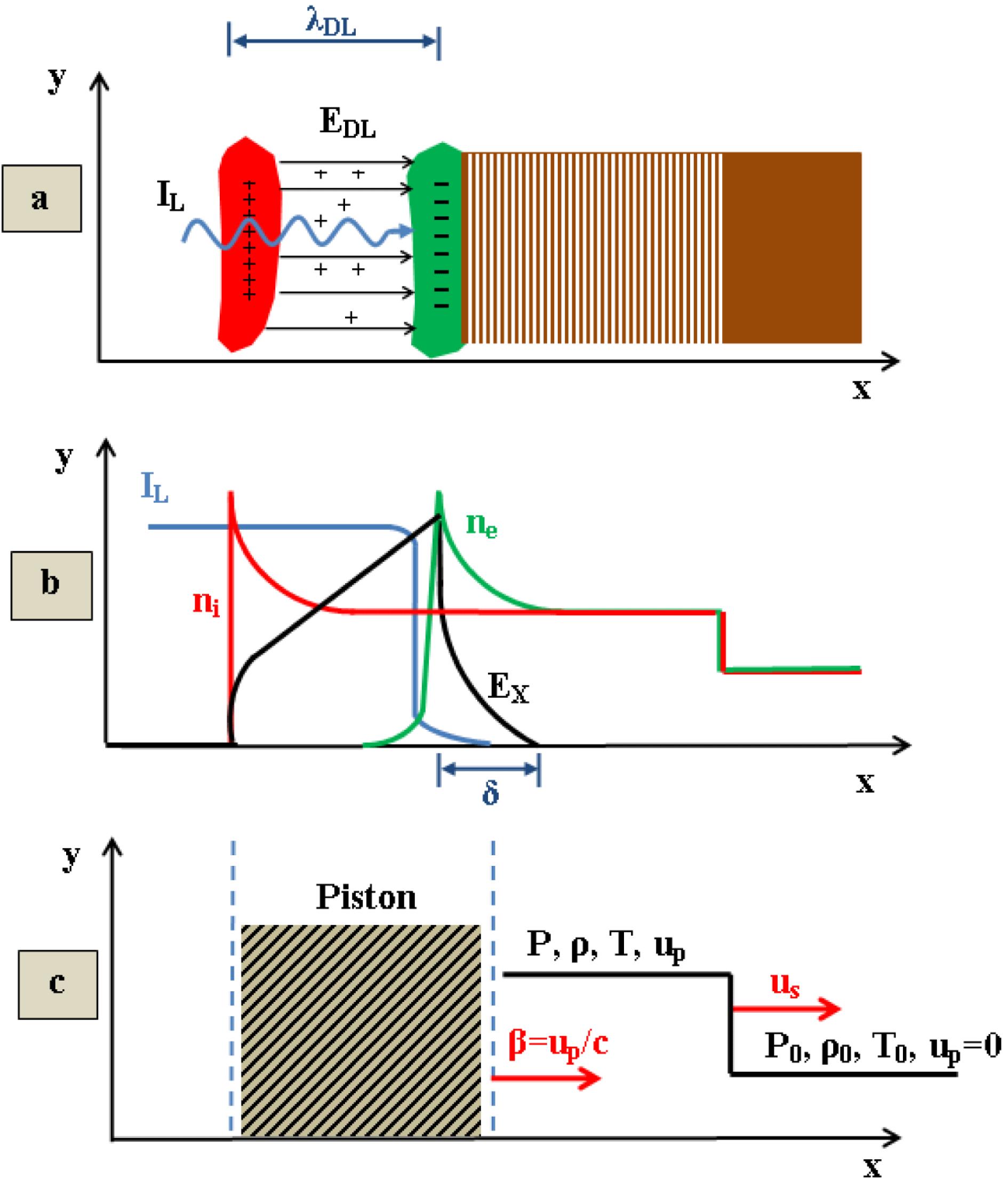
Fig. 1. (a) Displays the capacitor model where the ponderomotive force dominates the interaction; (b) shows the DL of the negative and positive charges. (c) The shock wave description in the laboratory frame of reference.
![The shock wave compression $\unicode[STIX]{x1D705}=\unicode[STIX]{x1D70C}/\unicode[STIX]{x1D70C}_{0}$ as a function of the dimensionless shock wave pressure $\unicode[STIX]{x1D6F1}=P/\unicode[STIX]{x1D70C}_{0}c^{2}$ for $\unicode[STIX]{x1D6E4}=5/3$.](/richHtml/hpl/2016/4/3/03000e25/img_2.gif)
Fig. 2. The shock wave compression $\unicode[STIX]{x1D705}=\unicode[STIX]{x1D70C}/\unicode[STIX]{x1D70C}_{0}$ as a function of the dimensionless shock wave pressure $\unicode[STIX]{x1D6F1}=P/\unicode[STIX]{x1D70C}_{0}c^{2}$ for $\unicode[STIX]{x1D6E4}=5/3$ .
Fig. 3. The dimensionless shock wave pressure $\unicode[STIX]{x1D6F1}=P/(\unicode[STIX]{x1D70C}_{0}c^{2})$ versus the dimensionless laser irradiance $\unicode[STIX]{x1D6F1}_{L}=I_{L}/(\unicode[STIX]{x1D70C}_{0}c^{3})$ in the domain $10^{-4}<\unicode[STIX]{x1D6F1}_{L}<1$ . The inserted table shows numerical values in the area $10^{-4}<\unicode[STIX]{x1D6F1}_{L}<10^{-2}$ .
Fig. 4. The dimensionless shock wave velocity $u_{s}/c$ and the particle velocity $u_{p}/c$ in the laboratory frame of reference versus the dimensionless laser irradiance $\unicode[STIX]{x1D6F1}_{L}=I_{L}/(\unicode[STIX]{x1D70C}_{0}c^{3})$ in the domain $10^{-4}<\unicode[STIX]{x1D6F1}_{L}<1$ . The inserted table shows numerical values in the area $10^{-4}<\unicode[STIX]{x1D6F1}_{L}<10^{-2}$ .
Fig. 5. (a) The speed of sound in units of speed of light, $c_{S}/c$ and (b) the ratio of shock velocity to the rarefaction velocity, $u_{s}/c_{rw}$ as a function of the dimensionless laser irradiance $\unicode[STIX]{x1D6F1}_{L}=I_{L}/(\unicode[STIX]{x1D70C}_{0}c^{3})$ .
Fig. 6. Micro-foil velocity as a function of laser pulse duration $t$ in units of of $\unicode[STIX]{x1D70F}=\unicode[STIX]{x1D70C}_{0}c^{2}l/(2I)$ , where $\unicode[STIX]{x1D70C}_{0}$ is the initial density, $l$ is the foil thickness and $I$ is the laser intensity [$\text{erg}/(\text{s}~\text{cm}^{2})$ ]. (a) Laser pulse duration up to $15\unicode[STIX]{x1D70F}$ , (b) laser pulse duration up to $500\unicode[STIX]{x1D70F}$ .
Fig. 7. Flow ($u_{p0}$ , $u_{p1}=u_{p2}$ ) and shock waves ($u_{s1}$ , $u_{s2}$ ) velocities after impact of flyer and target in the laboratory frame of reference. The flow velocities ($v_{0}$ , $v_{1}$ , $v_{2}=v_{1}$ , $v_{3}=v_{0}$ ) are also defined in the shock wave reference frames S1 and S2. The lower figure shows a schematic picture before collision.
Fig. 8. The compressions of the shocked target $\unicode[STIX]{x1D705}_{1}$ and the shocked flyer $\unicode[STIX]{x1D705}_{2}$ for $\unicode[STIX]{x1D70C}_{0t}/\unicode[STIX]{x1D70C}_{0f}=K=1000$ .
Fig. 9. The pressures of the dimensionless shocked target $\unicode[STIX]{x1D6F1}_{1}$ and the shocked flyer $\unicode[STIX]{x1D6F1}_{2}$ for $\unicode[STIX]{x1D70C}_{0t}/\unicode[STIX]{x1D70C}_{0f}=K=1000$ .
Fig. 10. The shock and particle velocities accordingly, $u_{s}$ and $u_{p}$ , for $\unicode[STIX]{x1D70C}_{0t}/\unicode[STIX]{x1D70C}_{0f}=K=1000$ .
Fig. 11. Contours of equal $\unicode[STIX]{x1D70C}\cdot R$ as a function of ions and electrons temperatures for DT.
Fig. 12. Electrons $T_{e}$ and protons $T_{i}$ temperatures as a function of time for a DT case satisfying the ignition criterion.
Fig. 13. The fast ignition scheme by the impact of a high irradiance laser accelerated foil. (a) The pre-compression by the nanosecond laser beams. (b)–(d) The sequence of shock waves leading to the ignition hot spot.
Fig. 14. The fast ignition scheme of a detonation wave.
Fig. 15. The fusion energy $Q$ per unit mass released in the shock wave forward direction as a function of time in the shocked volume for (a) $\unicode[STIX]{x1D6E4}=3$ and (b) $\unicode[STIX]{x1D6E4}=5/3$ .

Set citation alerts for the article
Please enter your email address
© Copyright 2018-2021 | Chinese Laser Press. All Rights Reserved 沪ICP备15018463号-20