
Fangming Liu, Jiarui Lin, Yanbiao Sun, Jigui Zhu. Calibration Method for Stereo Phase Measuring Deflectometry System[J]. Laser & Optoelectronics Progress, 2020, 57(5): 051202
- Laser & Optoelectronics Progress
- Vol. 57, Issue 5, 051202 (2020)
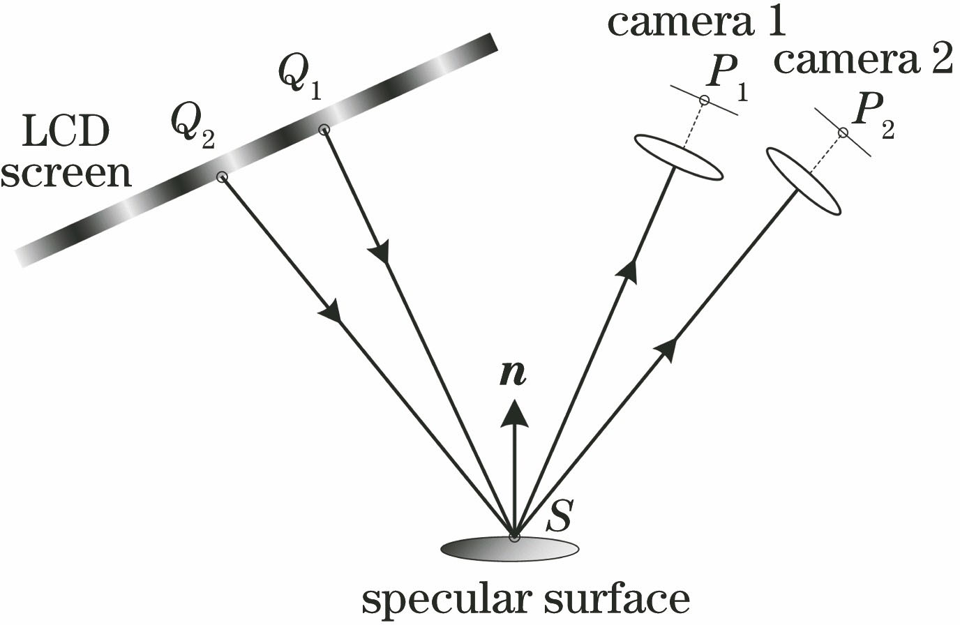
Fig. 1. Schematic of stereo phase measuring deflectometry system
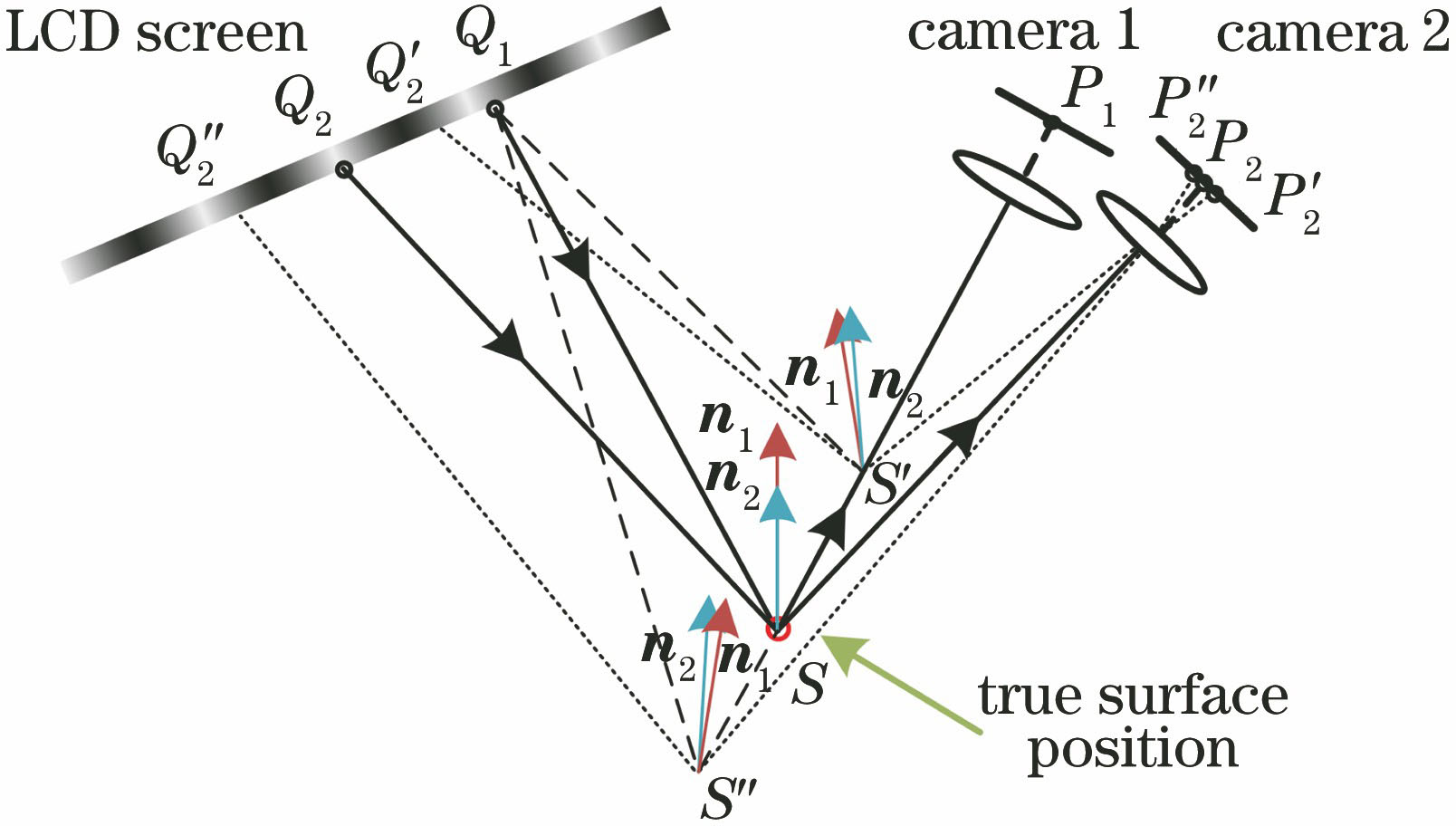
Fig. 2. Camera matching principle of stereo phase measuring deflectometry
Fig. 3. Schematic of transformation relationships among different coordinate systems
Fig. 4. Coordinate calibration for retro-reflectors in screen coordinate system
Fig. 5. Schematic of posture calibration of screen and camera
Fig. 6. Experimental setup diagram of coordinate calibration of retro-reflectors
Fig. 7. Picture of system calibration
Fig. 8. Picture of measurement experiment
Fig. 9. Surface reconstruction results of gauge blocks
Fig. 10. Reconstruction flatness of gauge block surfaces
Fig. 11. Picture of mirror to be measured
Fig. 12. Measurement results of mirror. (a) Result of mirror surface reconstruction; (b) result of surface flatness error
|
Table 1. Calibration results of intrinsic parameters of cameras
|
Table 2. Coordinates of retro-reflectors in screen coordinate system

Set citation alerts for the article
Please enter your email address
© Copyright 2018-2021 | Chinese Laser Press. All Rights Reserved 沪ICP备15018463号-20