
Na Zhang, Xizheng Ke, Xunfeng Yuan, Lijun Li. Research of adaptive modulation STBC-OCT precoding in MIMO-OFDM VLC system[J]. Infrared and Laser Engineering, 2022, 51(6): 20210652
- Infrared and Laser Engineering
- Vol. 51, Issue 6, 20210652 (2022)
Abstract
Keywords
0 Introduction
Visible light communication (VLC) takes the characteristics of rich spectrum resources, security and green energy saving compared with traditional wireless communication, and is a major development trend of future mobile communication wireless network, which can be promoted and applied in smart home, intelligent transportation and wireless access scenarios. VLC is the "last mile" wireless service delivery for its indoor environment, the data rate is limited by the modulation bandwidth of the LED[1-2], which is the main problem, signals modulated at high-frequencies are strongly attenuated by VLC[3], as a result, orthogonal frequency division multiplexing (OFDM) and multiple-input multiple-output (MIMO) techniques have been proposed to be combined to form a MIMO-OFDM system. OFDM can overcome the inter-symbol interference (ISI) and improve spectral efficiency great effectively by decomposing the channel into multiple orthogonal sub-channels[4-5], while MIMO can improve the channel capacity and data rate by equipping multiple transmitters and receivers simultaneously[6-7]. Usually, signal-to-noise ratio(SNR) of high-frequency channels is worse than that of the low-frequency channels in VLC system, so an adaptive OFDM modulation scheme is proposed to improve the data rate[8]. The channel matrix correlation of MIMO VLC systems is usually very high, so space-time block code (STBC) is proposed[9-10]. The high peak-to-average power ratio (PAPR) has always been a problem in OFDM signal, orthogonal circulant matrix transform (OCT) is proposed to achieve a relatively flat and higher SNR curve, the bit error rate (BER) performance of the system is improved to suppress the channel multipath fading, high-frequency fading [11-12] and the PAPR[13-14].
The contribution of the paper is to build adaptive modulation STBC-OCT precoding in MIMO-OFDM VLC System. Different from the existed works, it can reduce channel correlation, achieve relatively flat and higher SNR values by using STBC-OCT precoding, make full use of spectrum resources and improve data rate by using adaptive modulation in the system. Finally, a 2×2 MIMO-OFDM VLC system by using the adaptive modulation STBC-OCT precoding is setup, which anti-fading performance, BER performance and PAPR performance of the MIMO-OFDM VLC system without precoding, with STBC precoding, with OCT precoding and with proposed adaptive modulation STBC-OCT precoding is investigated experimentally for different modulation modes, DC bias (DC) and driving peak-to-peak voltages (VPP). The experimental results show that the proposed scheme can obtain the best BER performance compared with other methods, and is always lower than the 7% pre-forward error correction (pre-FEC) threshold of 3.8×10⁻³ with the transmission distance is 0.5 m, DC is 2.7 V and Vpp is 2.7-2.8 V, which can effectively overcome the bandwidth limitation of MIMO-OFDM VLC system and provide the best reliability.
1 Principle
1.1 Adaptive modulation STBC-OCT precoding scheme based on MIMO-OFDM VLC
An efficient adaptive modulation STBC-OCT precoding scheme is proposed due to the problems of high both of channel matrix correlation and PAPR in MIMO-OFDM VLC system, where STBC can robustness to the channel correlation, OCT can reduce the correlation of input sequence by using ZC matrix to suppress high PAPR, and propagate the information on each subchannel to all subchannels to achieve frequency diversity and obtain a relatively flat SNR to improve the BER performance of the system [12].
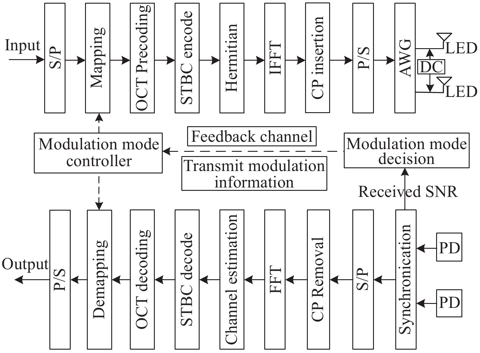
In order to simplify the analysis and not lose generality, taking two transmitters and two receivers as an example. Figure 1 is the principle block diagram of adaptive modulation STBC-OCT precoding scheme based on MIMO-OFDM VLC system. The principle process is as follows.
![]()
Figure 1.Block diagram of adaptive modulation STBC-OCT precoding scheme based on MIMO-OFDM VLC system
At the transmitter: Firstly the original random binary streams are through serial-to-parallel (S/P) conversion and the modulation mode and constellation mapping at the transmitter are selected adaptively according to the feedback channel, after the OCT precoding and STBC scheme the Hermite transform is performed to ensure that the signals are symmetrical in frequency domain[13]. Secondly, the inverse Fourier transform (IFFT) is used to ensure that the OFDM signals are real-valued in the time domain. The cyclic prefix (CP) is added to the OFDM symbol to overcome ISI, and the transmitted signals are generated which are sent to any signal generator to generate analog OFDM signals after parallel-to-serial (P/S) conversion. Finally, direct current (DC) is added to make the signals non-negative and then sent by two LEDs respectively.
At the receiver: Firstly, two photodetectors receive the optical signal and convert into electrical signal, then the synchronization is used to detect the initial position of each data, channel estimation and noise variance estimation, and calculate the SNR combining with setting BER threshold to get the modulation mode of each subchannel according to the estimation results, and transmitted to the transmitter through the feedback channel. Secondly, the time-domain signals are converted to the frequency-domain signals after serialparallel (S/P) conversion, CP removing and Fourier transform (FFT) operations. Finally, the original binary data stream is recovered by STBC decoding, OCT decoding, demapping and parallel-to-serial (P/S) conversion.
1.2 STBC-OCT precoding principle
In adaptive modulation STBC-OCT precoding, OCT precoding after the constellation mapping, where redistributes the noise on each subchannel to each subcarrier, so that the SNR value of each OFDM symbol is uniform.The circulant matrix is generated by ZC sequence, which has ideal periodic autocorrelation and low cross-correlation, so that the circulant matrix constructed has orthogonality. ZC sequence is defined as[15-16]:
Where
OFDM symbol after mapping can be expressed as:
The above
Where
Where
At the receiver, after CP removing and Fourier transform (FFT) operations the received signal is expressed as:
Where
1.3 Adaptive modulation scheme
The BER performance of the system is poor due to the high frequency channel attenuation in VLC system, so an adaptive modulation scheme is proposed. The basic thought is to calculate the SNR according to the result of noise variance estimation at the receiver, and then to get the maximum value of modulation mode and order of each sub-channel combined with the set BER threshold, and finally to feed back to the transmitter. Therefore, the low-order modulation with larger attenuation and high-order modulation with smaller attenuation on the subcarriers is adopted, which can make full use of the spectrum resources and improve the data rate.
So, the received SNR of the signal on the
Where the transmit power has been normalized,
Taking QAM as an example, the relationship between BER, SNR and modulation order is as follow[19]:
In equation (6), if BER0 is given, the modulation order of the
Where
1.4 PAPR performance
After OFDM, the time domain signal on the
Where
The PAPR of OFDM signal can be expressed as[12]:
In equation (9), the unit of PAPR is dB, which
The higher PAPR, the higher the probability of LED nonlinear distortion, and the worse BER performance of the system. The complementary cumulative distribution function (CCDF) is used to evaluate the performance of PAPR, it represents the probability that the PAPR of OFDM symbol exceeds the given threshold PAPR0:
2 Experimental setup and result analysis
The experimental setup of a 2×2 MIMO-OFDM VLC system is shown in Fig.2. At the transmitter, the generated signals are uploaded into an arbitrary function generator. DC offffset is also supplied by signal generator to ensure the positivity of the transmitted signals. Then, mixed signals are transmitted by two LEDs. At the receiver, the optical signals are converted into electrical signals by two photodetectors (PDs), which are recorded by a high-speed digital oscilloscope. The parameters used in the experiment are shown in Table 1.
![]()
Figure 2.Experimental setup of the proposed MIMO-OFDM VLC system
| System parameters | Values |
| Modulation order | 8 QAM、16 QAM、64 QAM |
| Bandwidth/MHz | 12.5 |
| FFT length | 1024 |
| Subcarrier number | 256 |
| CP length | 16 |
| Transmission distance/m | 0.5 |
| Distance between TXs/cm | 7 |
| Distance between RXs/cm | 10 |
Table 1. Experimental parameters
Figure 3 shows the BER curves of BPSK, QPSK, 8 QAM, 16 QAM and 64 QAM modulation respectively. The BER of the five modulation methods is gradually decreasing with the increase of SNR; SNR required for PSK modulation is smaller at the same BER level compared with QAM modulation; the BER of the system is also increasing with the increase of QAM modulation order; when BER is at the 7% pre-forward error correction (pre-FEC) threshold of 3.8×10⁻³, the SNR required for BPSK, QPSK, 8 QAM, 16 QAM and 64 QAM modulation are 3.8 dB, 7 dB, 9.6 dB, 13 dB and 20.7 dB; according to estimate of the SNR on the receiver, the modulation mode of the transmitter can be adaptively selected through the feedback channel, BPSK, QPSK or 8 QAM modulation is adopted if the SNR is small, otherwise 16 QAM or 64 QAM modulation. Under the same BER, it can greatly improve the utilization of frequency band adaptive modulation method compared with a certain fixed modulation method is used.
![]()
Figure 3.BER curve of adaptive modulation
Figure 4 shows the curves of the SNR with the subcarrier index in the traditional MIMO-OFDM system, STBC coding, OCT precoding and STBC-OCT precoding. In the traditional MIMO-OFDM, the SNR is reduced from 22 dB to 8 dB, and the higher-frequency fading is obvious, which is mainly caused by the nonlinear characteristics of the LED; the SNR of a single STBC code is reduced from 27 dB to 12 dB, and the average SNR is about 4 dB higher than that of traditional MIMO-OFDM. Therefore, it is beneficial for higher-frequency fading. However, the system using a single STBC code is still limited by bandwidth, and its SNR curve drops monotonously; a single OCT precoding has a SNR curve of about 14 dB within the subcarrier index range; STBC-OCT precoding still maintains the relatively flat SNR advantage of a single OCT precoding, and the SNR is increased by about 3 dB compared with OCT precoding, so it can effectively overcome the problem of bandwidth limitation in MIMO-OFDM VLC system.
![]()
Figure 4.SNR curves of different schemes of MIMO-OFDM VLC system
Figure 5 shows the simulation results of the CCDF curves of the traditional MIMO-OFDM system, STBC coding, OCT precoding and STBC-OCT precoding schemes. The PAPR performance is similar to the MIMO-OFDM system, STBC coding and OCT precoding, while the PAPR of the STBC-OCT precoding system is much lower. At the CCDF=10−4, the STBC-OCT precoding scheme was used to obtain a gain of 2 dB over the PAPR of the other three schemes.
![]()
Figure 5.CCDF curves of different PAPR schemes of MIMO-OFDM VLC system
BER is an important indicator to measure system performance, so the relationship between BER performance of MIMO-OFDM VLC system and driving peak voltage (Vpp) and direct current offset (DC) is further analyzed.
Figure 6 shows the BER of the traditional MIMO-OFDM, OCT precoding and STBC-OCT precoding schemes under different DC bias conditions. Using Rebel Star 01 LED, the LED’s starting light-emitting voltage is 2.2 V through experimental tests, and the LED has a good linearity in the range of 2.5 V to 2.9 V[14-15]. In the experiment, Vpp is set to 2.8 V, and the DC bias is 2.4-3.1 V, the BER of each curve shows a trend of first decreasing and then increasing with the DC bias increases. When the DC is 2.7 V, this value is exactly in the middle of the linear voltage region of the LED, so the error performance of the three curves is the best, and the BER are 5.45×10⁻¹, 2.3×10⁻¹, 8.8×10⁴. The STBC-OCT precoding has the best BER performance and is always lower than the 7% pre-FEC threshold of 3.8×10⁻³, which is mainly due to the flatness of the SNR, which reduces the higer-frequency attenuation error, thereby improving the BER performance of the system.
![]()
Figure 6.BER curves of different schemes of MIMO-OFDM VLC system at different DC
In addition, in the experiment, the DC offset is set to 2.7 V, and the Vpp-value is from 2.1 V to 3.3 V, the BER performance of different schemes is shown in Fig.7. The BER of each curve also shows a trend of first decreasing and then increasing with the increase of Vpp, When Vpp= 2.7 V, the BER of STBC-OCT precoding is 1×10⁻³, Vpp=3.1 V, the BER of MIMO-OFDM and OCT precoding are 2.6×10⁻³, 2.5×10⁻³, the STBC-OCT precoding performance is the best and it is lower than the 7% pre-FEC threshold of 3.8×10⁻³. Experimental results show that the BER decreases first with the increase of Vpp, because increasing Vpp can improve the SNR, Then the BER increases again, and when Vpp continues to increase, nonlinear distortion plays a leading role.
![]()
Figure 7.BER curves of different schemes of MIMO-OFDM VLC system at different
3 Conclusions
In this paper, an adaptive modulation STBC-OCT precoding scheme based on the MIMO-OFDM VLC system is proposed. The BER performance and PAPR performance of the MIMO-OFDM VLC system without precoding, with STBC precoding, with OCT precoding and with proposed adaptive modulation STBC-OCT precoding is investigated experimentally for different modulation modes, DC bias and driving peak-to-peak voltages (VPP). The experimental results show that by using adaptive modulation STBC-OCT precoding the uniform, high SNR value and a lower PAPR value is achieved over data subcarriers for the MIMO-OFDM VLC system compared with other existing schemes, which can effectively overcome the problem of bandwidth limitation of MIMO-OFDM VLC systems. Therefore, when the sample rate of AWG is 100 MS/s, transmission distance is 0.5 m, DC is 2.7 V, Vpp is 2.7-2.8 V, the BER performance using proposed scheme can be reduced to 8.8×10⁻⁴, which achieves better BER performance than other existing schemes, and below the BER threshold of 7% FEC. In summary, the proposed adaptive STBC-OCT precoding can be considered as a potential and suitable candidate for MIMO-OFDM VLC systems, which can significantly improve the reliability of the system.
References
[1] Deng P, Kavehrad M, Kashani M A . Nonlinear modulation acteristics of white LEDs in visible light communications[C]2015 Optical Fiber Communications Conference Exhibition (OFC), 2015: 13.
[2] D F Zhang, Y J Zhu, Y Y Zhang. Multi-LED phase-shifted OOK modulation based visible light communication systems. IEEE Photonics Technology Letters, 25, 2251-2254(2013).
[3] A Jovicic, J Li, T Richardson. Visible light communication: Opportunities, challenges and the path to market. IEEE Communications Magazine, 51, 26-32(2013).
[4] Q Hu, X Jin, Z Xu. Compensation of sampling frequency offset with digital interpolation for OFDM-based visible light communication systems. Journal of Lightwave Technology, 36, 5488-5497(2018).
[5] Li F, Zhang C. Perfmance analysis on hybrid OOKOFDM modulation in VLC system[C]IEEE International Symposium on Broadb Multimedia Systems Broadcasting, 2019: 1–5.
[6] Kumar A, Ghai S K. BER perfmance analysis of indo MIMOVLC system f multipath reflection[C]Technologies f SmartCity Energy Security Power, 2018: 1–5.
[7] L Deng, Y Fan. Analysis of channel correlation and channel capacity for indoor MIMO visible light communication systems. Applied Optics, 59, 4672-4684(2020).
[8] Y Hong, L K Chen. Toward user mobility for OFDM-based visible light communications. Optcial Lett, 41, 3763(2016).
[9] M L Tran, S Kim. Orientation-induced link-blocked receiver for MIMO visible light communication. Optcial Express, 28, 12157(2020).
[10] M Chen, H Lu, D Chen. An efficient MIMO–OFDM VLC system of combining space time block coding with orthogonal circulant matrix transform precoding. Optical Fiber Communications, 473, 125993(2020).
[11] C C Wei, F M Wu, Z Y Chen, et al. Indoor VLC system with multiple LEDs of different path lengths employin spacetime block-coded DMT/CAP modulation. Opt Networking, 7, 459-466(2015).
[12] X Guo, C Wang, W Wang. Experimental demonstration of Zadoff–Chu matrix transform precoding for MIMO-OFDM visible light communications. Advances in Condensed Matter Physics, 4343582(2020).
[13] X Guo, S Li, G Yang. Experimental demonstration of special-shaped 32-quadrature amplitude modulation constellations for visible light communications. Advances in Condensed Matter Physics, 7252795(2018).
[14] S A Liu, J He, Q H Chen. Experimental research of adaptive OFDM and OCT precoding with a high SE for VLLC system. Optical Fiber Technology, 37, 21-25(2017).
[15] Y Hong, J Xu. Experimental investigation of multi-band OCT precoding for OFDM-based visible light communications. Optics Express, 25, 12908-12915(2017).
[16] Y R Wei, J He, R Deng. An approach enabling adaptive FEC for OFDM in fiber-VLLC system. Optical Fiber Communications, 405, 329-333(2017).
[17] A Bansal, M R Bhatnagar, A Hjorungnes. Decoding and performance bound of demodulate and forward based distributed alamouti STBC. IEEE Transcations on Wireless Communications, 12, 702-713(2013).
[18] Y Jiang, M K Varanasi, J Li. Performance analysis of ZF and MMSE equalizers for MIMO systems: An in-depth study of the high SNR regime. IEEE Transaction Information Theory, 57, 2008-2026(2011).
[19] N Zhang, Q Q Ren, J Q He. MIMO-OFDM VLC system based on adaptive modulation,channel estimation and coding. Optical Communication Technology, 45, 59-62(2021).


Set citation alerts for the article
Please enter your email address

© Copyright 2018-2021 | Chinese Laser Press. All Rights Reserved 沪ICP备15018463号-20