
Jing Wang, Chengbao Liu, Lei Yang, Jian Shang, Zhiqing Zhang. Calculation of Geostationary Satellites' Nominal Fixed Grid and Its Application in FY-4A Advanced Geosynchronous Radiation Imager[J]. Acta Optica Sinica, 2018, 38(12): 1211001
- Acta Optica Sinica
- Vol. 38, Issue 12, 1211001 (2018)
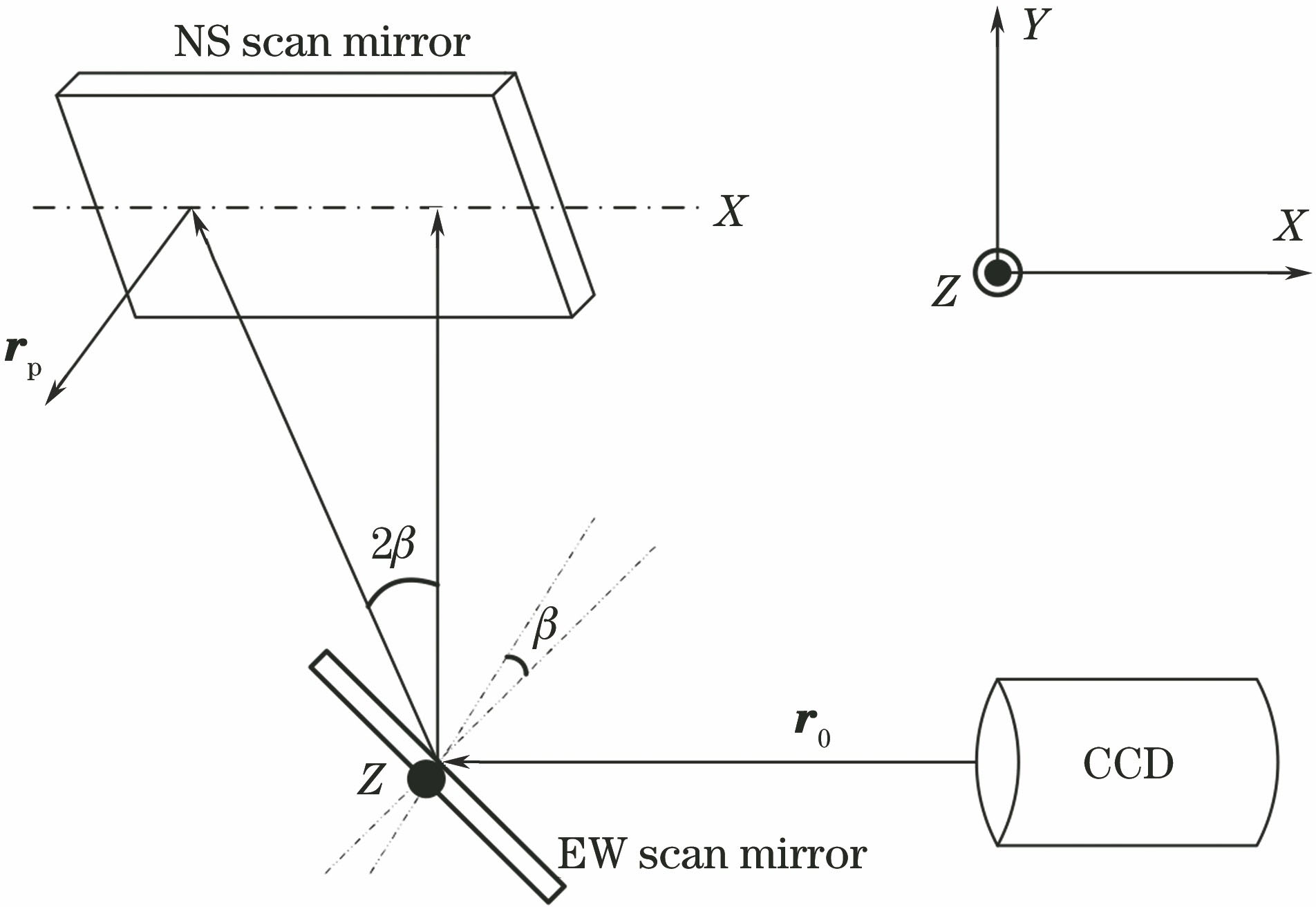
Fig. 1. Schematic of scanning mirror optical path of FY-4A imager
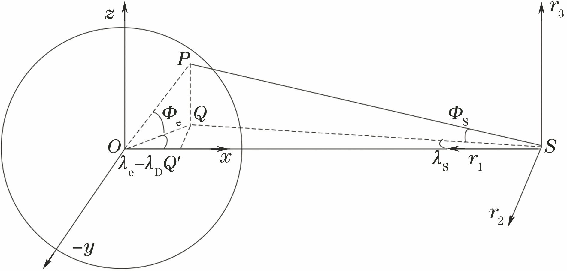
Fig. 2. Satellite coordinates defined in CGMS
Fig. 3. Satellite coordinates defined in GOES-R
Fig. 4. East-west and north-south pointing angles in CGMS and GOES-R
Fig. 5. (a) Caspian sea L1 image+CGMS coastline; (b) Caspian sea L1 image+GOES-R coastline; (c) Caspian sea transformed image+GOES-R coastline
Fig. 6. (a) Western coastline of Australia L1 image+CGMS coastline; (b) western coastline of Australia L1 image+GOES-R coastline; (c) western coastline of Australia transformed image+GOES-R coastline
Fig. 7. (a) Eastern coastline of Australia L1 image+CGMS coastline; (b) eastern coastline of Australia L1 image+GOES-R coastline; (c) eastern coastline of Australia transformed image+GOES-R coastline
Fig. 8. (a) Somalia L1 image+CGMS coastline; (b) Somalia L1 image+GOES-R coastline; (c) Somalia transformed image+GOES-R coastline
Fig. 9. (a) Western coastline of Java island L1 image+CGMS coastline; (b) western coastline of Java island L1 image+GOES-R coastline; (c) western coastline of Java island transformed image+GOES-R coastline
Fig. 10. (a) Sakhalin island L1 image+CGMS coastline; (b) Sakhalin island L1 image+GOES-R coastline; (c) Sakhalin island transformed image+GOES-R coastline
Fig. 11. Distribution of calculated coastlines on the full disk
Fig. 12. (a) Differences of east-west angles between FY-4A and GOES-R; (b) differences of north-south angles between FY-4A and GOES-R
Fig. 13. (a) Differences of east-west angles between FY-4A and CGMS; (b) differences of north-south angles between FY-4A and CGMS
|
Table 1. Scanning and stepping angles of normal fixed grid

Set citation alerts for the article
Please enter your email address
© Copyright 2018-2021 | Chinese Laser Press. All Rights Reserved 沪ICP备15018463号-20