
Weifeng Du, Yanqing Wang, Lihui Jiang, Xiaonan Mao, Nan Chen. Research on baffle detection technology for star sensor (invited)[J]. Infrared and Laser Engineering, 2023, 52(9): 20230450
- Infrared and Laser Engineering
- Vol. 52, Issue 9, 20230450 (2023)
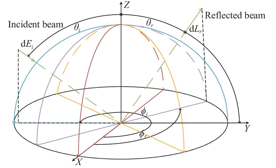
Fig. 1. BRDF measurement
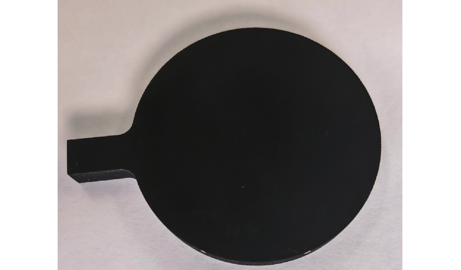
Fig. 2. Magic black matting coating
Fig. 3. Detection system of BRDF
Fig. 4. Fitting data of BRDF
Fig. 5. Schematic diagram of the edge
Fig. 6. Dual telecentric coaxial optical detection of light-blocking ring edges
Fig. 7. Analysis of image quality. (a) Distortion; (b) MTF
Fig. 8. Flow diagram of the algorithm for edge recognition and edge thickness calculation based on grayscale image
Fig. 9. Test system data calibration. (a) Reticle; (b) Measurement accuracy
Fig. 10. Schematic of edge inspection
Fig. 11. Measurement of mask edge by imaging method
Fig. 12. Light-blocking ring edge thickness test data
Fig. 13. Schematic diagram of mask extinction ratio test
Fig. 14. Baffle design parameters
Fig. 15. Extinction ratio detection
Fig. 16. Stray light test in darkroom
Fig. 17. Stray light test data
Fig. 18. Stray light test at outfield
Fig. 19. Stargazing test data. (a) Accuracy of star sensor without stray light; (b) Accuracy of star sensor interfered by stray light using the baffle mentioned in this paper
|
Table 1. Table of experimental conditions and techniques
|
Table 2. Table of experimental conditions and techniques

Set citation alerts for the article
Please enter your email address
© Copyright 2018-2021 | Chinese Laser Press. All Rights Reserved 沪ICP备15018463号-20