
Jian Luo, Haoran Wang, Xun Cai, Zhengqian Luo, Hongyan Fu. Temperature-sensing scheme based on a passively mode-locked fiber laser via beat frequency demodulation[J]. Chinese Optics Letters, 2023, 21(2): 020603
- Chinese Optics Letters
- Vol. 21, Issue 2, 020603 (2023)
Abstract
1. Introduction
Over the past decades, fiber-optic temperature sensors have received considerable attention due to their advantages of compact size, anti-electromagnetic interference, and low cost[1–4]. Such sensors have been widely applied in various fields, including environmental protection, food storage, health care, and industrial design. With the development of fiber-optic sensing technology, various temperature sensing structures have been proposed, like fiber Bragg gratings (FBGs)[5–7], Mach–Zehnder interferometers (MZIs)[8–10], Michelson interferometers (MIs)[11,12], and Fabry–Perot interferometers (FPIs)[13–15]. However, most of these sensing schemes are passive, resulting in low signal-to-noise ratio (SNR) and resolution. In recent years, benefiting from the narrow bandwidth, high resolution, and high SNR, fiber laser sensing schemes have been widely explored. Mandal et al. proposed a fiber-optic laser sensing probe for temperature sensing with the sensitivity of 12.01 pm/°C[16]. Gonzalez-Reyna et al. described a fiber ring laser used for temperature sensing where the FBG was used as the sensing head, and the temperature sensitivity was 18.8 pm/°C[17]. In order to improve the sensitivity of temperature sensors, Shi et al. proposed a fiber ring laser used for temperature sensing, in which the Sagnac loop served as the sensing head and the temperature sensitivity reached 1.739 nm/°C[18]. The demodulation system of these temperature-sensing schemes relies on expensive optical equipment, and the sensitivity and resolution of the sensing systems are limited. The beat frequency demodulation system is considered a fantastic method to realize the sensor’s demodulation, and it has attracted considerable research attention, since measurement in the electronic domain enjoys high speed, better resolution, and lower cost due to matured electronic technology. The beat frequency signal (BFS) is generated when the output optical signal of the fiber laser is transformed into an electrical signal by the photoelectric detector (PD). Therefore, the change in optical signal generated by the external environment will lead to a change in BFS. Consequently, tiny variations in the optical domain will lead to significant changes in the electronic domain. Recently, Yin et al. demonstrated a multilongitudinal-mode (MLM) fiber laser combined with the beat frequency demodulation system used for temperature sensing; the sensitivity of the temperature sensor reached 10.24 kHz/°C when the monitored BFS was at 1581.7 MHz[19]. Huang et al. reported a temperature sensor utilizing a multiplexed MLM fiber laser with the longitudinal mode beat frequency demodulation system, and the sensitivity was approximately [20]. Yu et al. described a temperature-sensing system by employing a polarimetric MLM fiber laser sensor, in which the temperature sensitivity reached [21]. However, the sensitivity of the sensor using normal fiber lasers for beat frequency was limited due to the limited number of longitudinal modes of normal fiber lasers and low SNR of the BFS at high frequency. Compared with normal fiber lasers, passively mode-locked fiber lasers have the advantages of more longitudinal modes and better SNR of BFS at high frequency, which shows great potential for sensing applications.
In this paper, we propose a temperature-sensing scheme utilizing a passively mode-locked fiber laser (MLFL) combined with the beat frequency demodulation system. The stable longitudinal mode of passively MLFL and the PD can produce a BFS with good quality. Furthermore, the sensing system includes an interrogation unit, which can convert small phase variations in the optical domain induced by environmental changes into large frequency shifts in the electronic domain, and electronic devices are used, which facilitates the measurement and reduces the whole system cost. In our experiment, the SNR reaches 50 dB when the BFS is around 5 GHz, and the temperature sensitivity is when the ratio of the sensing fiber to overall length of cavity is 5 m/12.5 m. The temperature sensitivity reaches for the beat frequency of 10 GHz with the ratio of 10 m/17.5 m, while the SNR of BFS is approximately 30 dB. Experimental results show the sensing scheme exhibits good linearity, high tailorable sensitivity, high SNR, and is considered to have great potential in agriculture, food storage, medicine, and other fields, which require high sensitivity and resolution[22,23].
2. Operation Principle and Experimental Setup
2.1. Experimental setup
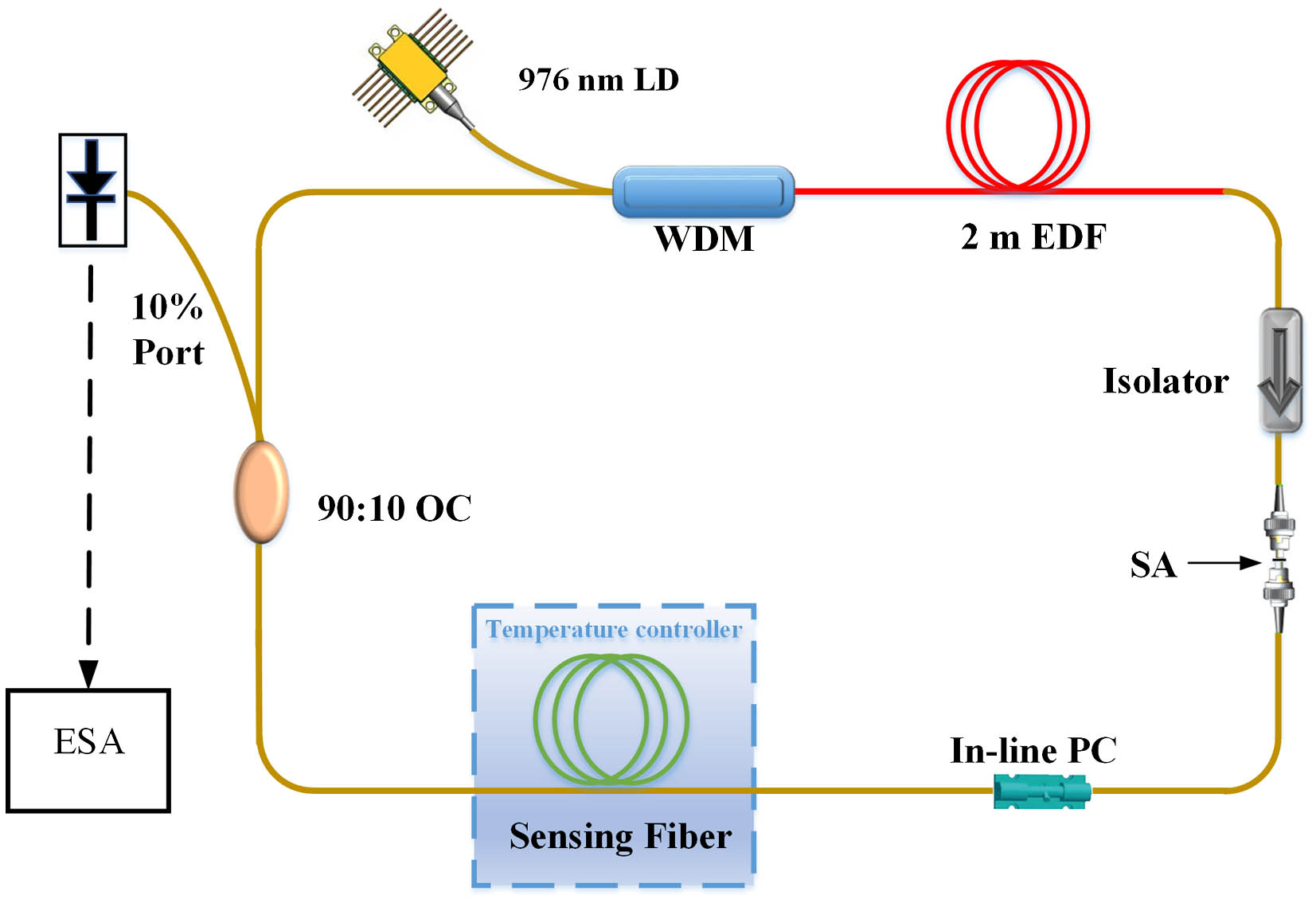
Figure 1 shows the experimental setup for temperature monitoring using passively MLFL combined with the beat frequency demodulation. The erbium-doped fiber (EDF, YOFC, M12-976/1550, absorption coefficient at 976 nm is 11 dB/m) with the length of 2 m is placed into the ring cavity acting as the gain medium and pumped by a 976 nm diode laser. The isolator (ISO) in the ring cavity is used to guarantee unidirectional operation. The carbon nanotube (CNT) in the ring cavity acts as a saturable absorber (SA) to compress pulses and achieve passive mode-locking operation. The polarization controller (PC) inserted into the cavity is to maintain the stable output of the passively MLFL. Different lengths of SMFs are inserted in the ring cavity, acting as the sensing head. The output light coming from the 10% port of the optical coupler (OC) is monitored by the optical spectrum analyzer (OSA, HP-7004A, resolution, 0.08 nm). The BFS is generated by the output light by the PD, and then detected by an electronic spectrum analyzer (ESA, HP, HEWLETT PICKARD 8593E).
Sign up for Chinese Optics Letters TOC. Get the latest issue of Chinese Optics Letters delivered right to you!Sign up now
![]()
Figure 1.Experimental setup of the proposed temperature sensor utilizing a passively MLFL combined with the beat frequency demodulation system.
2.2. Operation principle
In the ring cavity, the minimum signal of beat frequency generated by two adjacent laser modes can be expressed as[24]
In Eq. (1), is the vacuum speed of light, means the effective refractive index, and is the overall length of the cavity. It can be seen that is constant for a given cavity length. The BFS (with frequency of ) generated by arbitrary two laser modes can be expressed as
One can see that depends on the optical path of the ring cavity, , and the order . Therefore, the influence of temperature on the refractive index will lead to a shift of the BFS, which can be expressed as[25]
As shown in Eq. (5), the temperature sensitivity is affected by the BFS selected to be monitored, as well as the ratio of to . Therefore, by increasing the ratio of to and monitoring the higher BFS, the proposed sensor can obtain higher sensitivity. It should be noted that the ratio can only be close to 1 at most; the overall length of the cavity is used as the sensing unit, and the sensitivity reaches the maximum value.
3. Experimental Results and Discussions
Figure 2 illustrates the output characteristics of the proposed passively MLFL when the ratio of to is 5 m/12.5 m. Figure 2(a) shows the output optical spectrum of the passively MLFL under the pump power of 23 mW. It can be seen that the center wavelength of the proposed passively MLFL is 1565.9 nm, with a 3 dB spectral width of 4.5 nm. Figure 2(b) shows the output pulse train of the passively MLFL, and the pulse interval is approximately 44.5 ns. Figure 2(c) depicts the autocorrelation curve of the pulse, which is fitted by a hyperbolic secant function, and the soliton pulse width is 2.2 ps. As shown in Fig. 2(d), the repetition rate of the passively MLFL is 16.6 MHz, which corresponds to the laser cavity length of 12.5 m, and the SNR of the fundamental frequency is 63 dB.
![]()
Figure 2.Output characteristics of passively MLFL when the ratio of l to L is 5 m/12.5 m. (a) Optical spectrum; (b) pulse sequence; (c) autocorrelation curve; (d) RF spectrum.
The stability of the temperature sensor plays an essential role in the practical sensing applications. To investigate the stability of the temperature sensor based on the passively MLFL combined with the beat frequency demodulation system, the spectrum of the generated BFS is recorded every 10 min for 50 min by the ESA at room temperature; the results are shown in Fig. 3. First, the stability of BFS is measured at 5 GHz, and the spectra are shown in Fig. 3(a). The beat signal is stable during the observation time, and the SNR of the BFS reaches up to 50 dB. Subsequently, BFS at different frequencies is monitored, and the stability of the BFS over time is shown in Fig. 3(b). It can be seen that the frequency of the monitored signal is stable, as no frequency fluctuation can be observed in the period of measurement.
![]()
Figure 3.(a) Measured repeated spectrum of the monitored BFS every 10 min for 50 min; (b) frequency stability of the monitored BFS at 5 GHz, 10 GHz, and 15 GHz, respectively.
Then, the proposed temperature-sensing scheme based on a passively MLFL is applied for temperature monitoring. In our experiment, different temperature sensitivities are obtained by monitoring the different BFSs and employing the different ratios of to . Figures 4(a) and 4(b) represent the variations of the monitored BFS with temperature at 5 GHz and 15 GHz, respectively, when the ratio of to is 5 m/12.5 m. Figures 4(c) and 4(d) show the response curve of the frequency shift of the monitored BFS to the temperature variation, and one can see that the sensitivities of the proposed sensor are estimated to be and around 5 GHz and 15 GHz, respectively. It should be noted that by measuring the higher BFS, higher sensitivity can be obtained, which is consistent with Eq. (4).
![]()
Figure 4.Measured spectra of BFS around (a) 5 GHz and (b) 15 GHz under different temperatures and the linear fit between the frequency shift and temperature around (c) 5 GHz and (d) 15 GHz when the ratio of l to L is set to 5 m/12.5 m, respectively.
Based on Eq. (5), the length of sensing fiber has an important impact on the sensitivity, which is investigated in our experiment; the results are illustrated in Fig. 5. Figures 5(a) and 5(b) depict the measured spectra of the BFS around 10 GHz under different temperatures when the ratio of to is 5 m/12.5 m and 10 m/17.5 m, respectively. In addition, as shown in Fig. 5(b), the SNR of the BFS achieves 30 dB, which guarantees measurement with high accuracy, even at higher frequency. The relationship between the shift of BFS and temperature changes is shown in Fig. 5(c). The corresponding temperature sensitivities are estimated to be , with a good linearity of when the ratio of to is 5 m/12.5 m, and , with a good linearity of when the ratio of to is 10 m/17.5 m, respectively. Obviously, when the ratio of to is higher, the higher temperature sensitivity is obtained, which is consistent with the theoretical analysis. The frequency shift at 50 deg (10 m) is off the line compared with other data shown in Fig. 5(c), which is due to the measurement error.
![]()
Figure 5.Measured spectrum of the BFS around 10 GHz when the ratio of l to L is (a) 5 m/12.5 m and (b) 10 m/17.5 m, and (c) the response curve of the frequency shift to temperature variation.
Finally, our work is compared with other published temperature-sensing schemes, as shown in Table 1. One can see that our temperature-sensing scheme has higher sensitivity, higher SNR, and an easier sensor demodulation scheme.
| Ref. | Sensing head | Temperature range | Temperature sensitivity | SNR of the BFS | Demodulation method |
|---|---|---|---|---|---|
| [ | Sagnac interferometer | 21°C–50°C | 10.24 kHz/°C@1.58 GHz | Beat frequency | |
| [ | Single-mode fiber | 30°C–220°C | 16.78 kHz/°C@4.04 GHz | Beat frequency | |
| [ | EDF | 33°C–60°C | 5.2 kHz/°C@1.36 GHz | Beat frequency | |
| [ | MZI | 20°C–32°C | 0.16 nm/°C | / | Wavelength |
| [ | FBG | 15°C–60°C | 0.22 dB/°C | / | Intensity |
| Our work | Single-mode fiber | 20°C–80°C | Beat frequency |
Table 1. Comparison with Various Optical Fiber Temperature Sensors
4. Conclusions
In summary, a temperature-sensing scheme based on a passively MLFL and beat frequency demodulation has been demonstrated in this paper. BFS with good quality generated by the passively MLFL is used for temperature sensing. In our experiment, the temperature sensitivity reaches for the beat frequency of 10 GHz when the ratio of to is set to 10 m/17.5 m. The SNR of BFS reaches 50 dB for the beat frequency of 5 GHz when the ratio is selected as 5 m/12.5 m. The experimental results show that the temperature sensitivity of the proposed temperature-sensing scheme is tailorable by utilizing BFSs with different frequencies or the sensing fibers with different lengths. The proposed sensor, benefiting from low cost, tailorable high sensitivity, good reliability, and broad practicability, has great potential in agriculture, food storage, medicine, and other fields.
References
[1] Q. Chen, D. N. Wang, F. Gao. Simultaneous refractive index and temperature sensing based on a fiber surface waveguide and fiber Bragg gratings. Opt. Lett., 46, 1209(2021).
[2] S. J. Mihailov. Fiber Bragg grating sensors for harsh environments. Sensors, 12, 1898(2012).
[3] S. J. Mihailov, D. Grobnic, C. Hnatovsky, R. B. Walker, P. Lu, D. Coulas, H. Ding. Extreme environment sensing using femtosecond laser-inscribed fiber Bragg gratings. Sensors, 17, 2909(2017).
[4] J. Militky, M. Kadulova, D. Ciprian, P. Hlubina. Fiber optic temperature sensing with enhanced sensitivity based on spectral interferometry. Opt. Fiber Technol., 33, 45(2017).
[5] P. Cheng, L. Wang, Y. Pan, H. H. Yan, D. W. Gao, J. Wang, H. S. Zhang. Fiber Bragg grating temperature sensor of cladding with SrTiO3 thin film by pulsed laser deposition. Laser Phys., 29, 025107(2019).
[6] X. Pan, Y. Dong, J. Zheng, J. Wen, F. Pang, Z. Chen, Y. Shang, T. Wang. Enhanced FBG temperature sensitivity in PbS-doped silica optical fiber. J. Light. Technol., 37, 4902(2019).
[7] D. N. Wang. Review of femtosecond laser fabricated optical fiber high temperature sensors. Chin. Opt. Lett., 19, 091204(2021).
[8] L. C. Li, L. Xia, Z. H. Xie, D. M. Liu. All-fiber Mach-Zehnder interferometers for sensing applications. Opt. Express, 20, 11109(2012).
[9] T. Q. Liu, J. Wang, Y. P. Liao, X. Wang, S. S. Wang. All-fiber Mach-Zehnder interferometer for tunable two quasi-continuous points’ temperature sensing in seawater. Opt. Express, 26, 12277(2018).
[10] Z. Zhang, Y. Y. Wang, M. Zhou, J. He, C. R. Liao, Y. P. Wang. Recent advance in hollow-core fiber high-temperature and high-pressure sensing technology. Chin. Opt. Lett., 19, 070601(2021).
[11] L. G. Abbas, H. Li. Temperature sensing by hybrid interferometer based on Vernier like effect. Opt. Fiber Technol., 64, 102538(2021).
[12] S. Wang, Y. W. Yang, P. T. Niu, S. Wu, S. H. Liu, R. B. Jin, P. X. Lu, X. W. Hu, N. L. Dai. Fiber tip Michelson interferometer for temperature sensing based on polymer-filled suspended core fiber. Opt. Laser Technol., 141, 107147(2021).
[13] C. He, C. Zhou, Q. Zhou, S. Y. Xie, M. Z. Xiao, J. J. Tian, Y. Yao. Simultaneous measurement of strain and temperature using Fabry–Pérot interferometry and antiresonant mechanism in a hollow-core fiber. Chin. Opt. Lett., 19, 041201(2021).
[14] K. Yang, J. He, Y. Wang, S. Liu, C. Liao, Z. Li, G. Yin, B. Sun, Y. Wang. Ultrasensitive temperature sensor based on a fiber Fabry–Pérot interferometer created in a mercury-filled silica tube. IEEE Photon. J., 7, 6803509(2015).
[15] J. Zhang, H. Liao, P. Lu, X. Jiang, X. Fu, W. Ni, D. Liu, J. Zhang. Ultrasensitive temperature sensor with cascaded fiber optic Fabry–Perot interferometers based on Vernier effect. IEEE Photon. J., 10, 6803411(2018).
[16] J. Mandal, S. Pal, S. Tong, K. T. V. Grattan, A. T. Augousti, S. A. Wade. Bragg grating-based fiber-optic laser probe for temperature sensing. IEEE Photon. Technol. Lett., 16, 218(2004).
[17] M. A. Gonzalez-Reyna, E. Alvarado-Mendez, J. M. Estudillo-Ayala, E. Vargas-Rodriguez, M. E. Sosa-Morales, J. M. Sierra-Hernandez, D. Jauregui-Vazquez, R. Rojas-Laguna. Laser temperature sensor based on a fiber Bragg grating. IEEE Photon. Technol. Lett., 27, 1141(2015).
[18] J. Shi, Y. Wang, D. Xu, H. Zhang, G. Su, L. Duan, C. Yan, D. Yan, S. Fu, J. Yao. Temperature sensor based on fiber ring laser with Sagnac loop. IEEE Photon. Technol. Lett., 28, 794(2016).
[19] Z. Yin, L. Gao, S. Liu, L. Zhang, F. Wu, L. Chen, X. Chen. Fiber ring laser sensor for temperature measurement. J. Light. Technol., 28, 3403(2010).
[20] L. Huang, P. Wang, L. Gao, T. T. Zhang, X. F. Chen. Multiplexed multi-longitudinal mode fiber laser sensor. Opt. Express, 22, 25722(2014).
[21] X. J. Yu, X. Dong, X. F. Chen, J. T. Zhang, S. C. Liu. Polarimetric multilongitudinal mode fiber laser for simultaneous measurement of strain and temperature. J. Light. Technol., 34, 4941(2016).
[22] Y. Liu, L. Ma, C. Yang, W. Tong, Z. He. Long-range Raman distributed temperature sensor with high spatial and temperature resolution using graded-index few-mode fiber. Opt. Express, 26, 20562(2018).
[23] J. J. Tian, Z. G. Li, Y. X. Sun, Y. Yao. High-sensitivity fiber-optic strain sensor based on the Vernier effect and separated Fabry–Perot interferometers. J. Light. Technol., 37, 5609(2019).
[24] J. Tian, M. J. Hou, Y. Jiang, H. Luo, C. Y. Tang. Fiber ring laser cavity for strain sensing via beat frequency demodulation. Opt. Commun., 476, 126326(2020).
[25] J. Luo, X. Cai, H. R. Wang, H. Y. Fu. Temperature sensing technique by using a microwave photonics filter based on an actively mode-locked fiber laser. Microwave Opt. Technol. Lett., 63, 2535(2021).
[26] S. Chang, C. C. Hsu, T. H. Huang, W. C. Chuang, Y. S. Tsai, J. Y. Shieh, C. Y. Leung. Heterodyne interferometric measurement of the thermo-optic coefficient of single mode fiber. Chin. J. Phys., 38, 437(2010).
[27] L. Huang, L. Qian, L. Chen, L. Gao, X. Chen. Multilongitudinal mode fiber laser sensor for temperature measurement. Asia Communications and Photonics Conference (ACP), 1(2012).
[28] X. X. Tong, Y. X. Shen, X. W. Mao, C. Yu, Y. Guo. Fiber-optic temperature sensor based on beat frequency and neural network algorithm. Opt. Fiber Technol., 68, 102783(2022).
[29] W. H. Lin, L. Y. Shao, M. I. Vai, P. P. Shum, S. Q. Liu, Y. B. Liu, F. Zhao, D. R. Xiao, Y. H. Liu, Y. D. Tan, W. Z. Wang. In-fiber Mach–Zehnder interferometer sensor based on Er doped fiber peanut structure in fiber ring laser. J. Light. Technol., 39, 3350(2021).
[30] B. Yin, S. H. Wu, M. G. Wang, W. Q. Liu, H. S. Li, B. L. Wu, Q. C. Wang. High-sensitivity refractive index and temperature sensor based on cascaded dual-wavelength fiber laser and SNHNS interferometer. Opt. Express, 27, 252(2019).

Set citation alerts for the article
Please enter your email address
© Copyright 2018-2021 | Chinese Laser Press. All Rights Reserved 沪ICP备15018463号-20