
Qiang LIU, Zaiyuan WANG, Jiehao WANG, Yuhang LI. Research Progress on Low-noise Laser for Space-based Gravitational Wave Detector(Invited)[J]. Acta Photonica Sinica, 2022, 51(7): 0751409
- Acta Photonica Sinica
- Vol. 51, Issue 7, 0751409 (2022)
![Schematic of space-based gravitational wave detector constellations[13]](/richHtml/gzxb/2022/51/7/0751409/img_01.jpg)
Fig. 1. Schematic of space-based gravitational wave detector constellations[13]
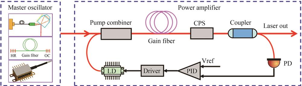
Fig. 2. Schematic of low-noise MOPA laser
Fig. 3. Schematic of NPRO
Fig. 4. HSL prototype for NGGM at NPL laboratories
Fig. 5. Delivered m-NPRO packages and photo of the baseline fiber amplifier
Fig. 6. RIN and frequency noise of fiber laser and NPRO
Fig. 7. RIN and frequency noise of PW-ECL and NPRO
Fig. 8. Schematic layout and photograph of the micro-integrated PW-ECL
Fig. 9. The first prototype of a laser for LISA
Fig. 10. Schematic diagram of I2-stabilized laser for DECIGO
Fig. 11. Schematic diagram of fiber amplifier for DECIGO
Fig. 12. DBR laser head and schematic of the internal structure for Tianqin-1 mission
Fig. 13. Principle diagram of laser source for Taiji-1 satellite
Fig. 14. Schematic of suppressing the intensity noise based on optoelectronic feedback control
Fig. 15. Schematic of the experimental setup and measurement of the RPN
Fig. 16. Low-noise laser developed by Tsinghua University
Fig. 17. Schematic of the PDH laser frequency stabilization
Fig. 18. Frequency noise spectral density between the PDH and the molecular iodine
|
Table 1. Design parameters for space-based gravitational wave detectors
|
Table 2. Key parameters of low-noise lasers for space-based gravitational wave detector

Set citation alerts for the article
Please enter your email address
© Copyright 2018-2021 | Chinese Laser Press. All Rights Reserved 沪ICP备15018463号-20