Abstract
Ultrafast lasers generating high-repetition-rate ultrashort pulses through various mode-locking methods can benefit many important applications, including communications, materials processing, astronomical observation, etc. For decades, mode-locking based on dissipative four-wave-mixing (DFWM) has been fundamental in producing pulses with repetition rates on the order of gigahertz (GHz), where multiwavelength comb filters and long nonlinear components are elemental. Recently, this method has been improved using filter-driven DFWM, which exploits both the filtering and nonlinear features of silica microring resonators. However, the fabrication complexity and coupling loss between waveguides and fibers are problematic. We demonstrate a tens- to hundreds- of gigahertz-stable pulsed all-fiber laser based on a hybrid plasmonic microfiber knot resonator device. Unlike previously reported pulse generation mechanisms, the operation utilizes the nonlinear-polarization-rotation (NPR) effect introduced by the polarization-dependent feature of the device to increase intracavity power for boosting DFWM mode-locking, which we term NPR-stimulated DFWM. The easily fabricated versatile device acts as a polarizer, comb filter, and nonlinear component simultaneously, thereby introducing an application of microfiber resonator devices in ultrafast and nonlinear photonics. We believe that our work underpins a significant improvement in achieving practical low-cost ultrafast light sources.
1 Introduction
High-repetition-rate pulsed lasers have garnered considerable attention during recent decades for applications in optical communications,1 microwave photonics,2 generation of frequency combs,3 and spectroscopy.4 However, as the most extensively used pulsed laser source, mode-locked fiber laser typically produces pulse trains with fundamental repetition rates well below 1 GHz, owing to the limitations of the laser cavity’s length. Therefore, several methods for enhancing repetition rates have been proposed, including direct approaches such as active mode-locking5 or shortening of cavity length,6 although the repetition rates were still below 20 GHz7 with degraded pulse quality due to a decline in intracavity energy. Passive harmonic mode-locking methods proposed subsequently increase the repetition rates of pulsed lasers up to tens of gigahertz by producing multiple pulses in each round trip,8,9 and the harmonic mode-locking operation is hardly controllable.
Yoshida and Nakazawa10 demonstrated a new approach for generating 115 GHz pulse trains, in which a Fabry–Pérot filter and 1.5-km dispersion-shifted fiber were incorporated in the main cavity. The underlying mechanism is called dissipative four-wave-mixing (DFWM),11 and its key components comprise both multiwavelength filters and high-nonlinearity elements. Since then, a number of demonstrations of high-repetition-rate pulse trains adopting such a method have been reported, exploiting various devices, such as fiber Bragg gratings,12 Mach-Zehnder interferometers,13 and silicon microring resonators.14 Peccianti et al.15 proposed a stable 200-GHz ultrafast fiber laser based on a silica microring resonator. The resonator serves as both a comb filter and high-nonlinearity element to boost DFWM mode locking; thus they termed the mechanization filter-driven DFWM (FD-DFWM). Nevertheless, the silicon/silica scheme often involves high cost and significant coupling loss between the fiber and the silicon/silica-waveguide. Therefore, a low-cost all-fiber resonator for generating high-repetition-rate pulse fiber lasers using DFWM is desired. Nevertheless, strong nonlinearity is required to trigger short pulse generation.
Owing to advantages of strong evanescent field, low insertion loss, as well as compatibility to all-fiber optical systems, microfiber-based devices have been widely used, especially for microfiber resonators.16–18 It is noteworthy that, with significantly smaller diameters and air cladding, tapered microfibers exhibit high nonlinearity compared with common single-mode fibers (SMFs); a microfiber’s nonlinear coefficient is calculated to be at 1550 nm,19 which is 50 times that of the standard SMF, although still lower than silicon/silica waveguides’ 110 to .15,20 Hence microfiber can be combined with two-dimensional materials for nonlinearity enhancement;21 however, saturable absorption and additional insertion losses would be introduced.
Sign up for Advanced Photonics TOC. Get the latest issue of Advanced Photonics delivered right to you!Sign up now
Herein, we report a ring fiber laser incorporating a hybrid plasmonic microfiber knot resonator (HPMKR) applied to generate pulses up to 144.3 GHz at 1550 nm. The large polarization-dependent loss (PDL) of the HPMKR results in the nonlinear polarization rotation (NPR) of the laser cavity, yielding a Q-switched or mode-locked pulse with large instantaneous power to compensate relatively low nonlinearities and excite DFWM in the microfiber. For its versatile role in fiber lasers, we tend to term the laser scheme as NPR-stimulated DFWM. The salient point is that the HPMKR is not only a broadband polarizing element but also a filter. The laser oscillates in stark contrast to all previous DFWM schemes, where the necessity of extremely high-nonlinearity elements is removed. In addition, the complexity hindering high-Q (of the order of a million) device fabrication may be removed, thereby lowering the bar for achieving DFWM effectively.
2 Results
2.1 Fabrication and Polarization Features of HPMKR
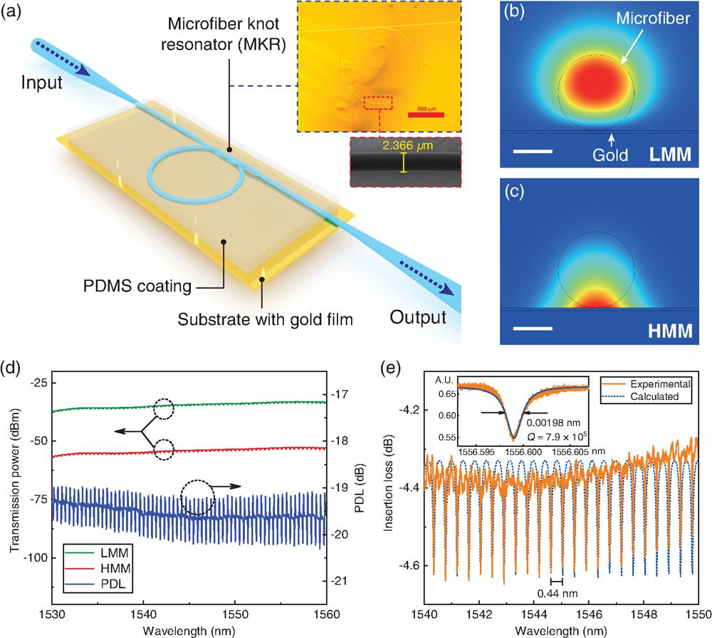
The key device of the laser, HPMKR, shown in Fig. 1(a) exhibits a concise structure. A knot resonator formed from tapered microfiber was attached to a glass substrate with a gilded surface and then packaged with polydimethylsiloxane (PDMS) polymer (specific fabrication process provided in Appendix). After the complete solidification of PDMS, the HPMKR turns into a stable device with steady properties to be characterized. As for the ring resonator, the resonant condition can be expressed as , where is the effective refractive index, is the ring section’s length of MKR, is the resonant wavelength, and is an integer. From this equation and the coupled mode theory, the intensity transmittance of the MKR can be derived as22where , , , and denote the mode-coupling coefficient of the coupling region, the coupling length, the intensity-insertion loss coefficient, and the intensity attenuation coefficient of the MKR, respectively. To experimentally verify the spectral response of the HPMKR, amplified spontaneous emission (ASE) light at 1550 nm was injected into the device; Fig. 1(e) shows a typical transmission spectrum of the hybrid device, where the -factor is measured to be (see Appendix for -factor measuring details), which is rather high for an MKR. With more precise control and optimization of coupling and loss, we believe the -factor of MKR is possible to be improved by an order of magnitude under current fabricating methods.

Figure 1.HPMKR design and characterization. (a) Schematic of the central component—a (–) microfiber ring resonator (with fiber pigtails) attached to gold film and coated with PDMS. Insets show the optical and SEM microscopic pictures of a typical sample that has a ring diameter of 1.1 mm and fiber diameter of 2.4 μm. The red scale bar represents 500 μm. (b), (c) Cross-section electric field modal distribution for a TE (LMM) and TM (HMM) polarized beam calculated using the finite element method. The scale bar represents 1.25 μm. Gold and microfiber are denoted in the plots and the ambience is PDMS. (d) Typical polarization dependent loss (PDL) of HPMKR at C-band. (e) Exemplary transmission spectra of HPMKR acquired by optical spectrum analyzer and theoretical calculations. The inset provides measurements of this sample’s -factor up to .
Considering the surface plasmon polaritons (SPPs) introduced by gold, certain polarization-dependent features should appear owing to the structure’s lack of circular symmetry. As the ring section establishes contact with the metal surface, the coupling between the plasmonic mode supported by the gold film and the waveguide modes results in a hybrid plasmonic mode (transverse-magnetic-like mode).23 The high-metal-coupling-loss mode and low-metal-coupling-loss mode will exhibit different losses during propagation in the HPMKR. Using the finite element method, we can numerically investigate the polarization-related mechanism; Figs. 1(b) and 1(c) show the cross-section electric field distributions of both modes. The diameter of the microfiber is , the thickness of gold film 100 nm, and the refractive indexes of gold and PDMS and 1.3997, respectively (both at the wavelength of 1550 nm).
Next, we measured the PDL of the device. Light from an ASE light source operating at 1550 nm was linearly polarized by a polarizer; subsequently a polarization controller (PC) was used to adjust the polarization state of light injected into the HPMKR, in which different optical modes in the HPMKR can be excited selectively. An optical spectrum analyzer (OSA, Yokogawa, AQ6370C) was employed to record the transmission spectrum. Figure 1(d) shows the largest PDL of HPMKR sample that we measured experimentally, whose value reaches up to 19.75 dB at 1550 nm, implying the device’s great potential as a polarizer. For comparison, a commercial polarization-dependent isolator usually has a PDL of (IO-G-1550-APC, Thorlabs).
2.2 Laser Scheme and Operation
The experimental setup is shown in Fig. 2. The HPMKR sample was embedded in a standard erbium-doped fiber (EDF) ring laser cavity. The EDF (OFS RightWave® EDF80) features a dispersion of , providing active gain for operation at 1550-nm waveband. The fibers comprising the remaining cavity are all SMFs. The length of the EDF and SMF can be adjusted to investigate the laser’s operation status under different net dispersions. A polarization-independent isolator was employed to force the pulse to circulate unidirectionally, and two PCs act on the pulse polarization state as the HPMKR is a polarization-sensitive device. The waveform at the 20% output of the optical coupler is monitored with an autocorrelator (A.P.E, pulseCheck-50) to measure the pulse duration, in addition to an OSA and a 200-MHz photodetector connected with an oscilloscope and radio frequency spectrum analyzer.
Figure 2.Schematic of the fiber laser based on HPMKR. The HPMKR sample in Fig. 1(e) is embedded in a loop cavity containing a wavelength division multiplexer (WDM), erbium-doped-fiber (EDF), and polarization-independent isolator (PI-ISO) to force the unidirectional operation, and two polarization controllers to act on the pulse polarization. Furthermore, 20% of the optical waveform was extracted by an 80:20 optical coupler (OC) out of the cavity and monitored by an autocorrelator, optical spectrum analyzer (OSA), and photodetector connected with an oscilloscope, as well as an RF spectrum analyzer (RSA).
Figure 3 shows the optical spectra [Figs. 3(a), 3(a-1), and 3(a-2)] and the time-domain traces of the pulsed output at different positions of PCs obtained by an oscilloscope [Figs. 3(b), 3(b-1), and 3(b-2)] and an autocorrelator [Figs. 3(c), 3(c-1), and 3(c-2)]. Here, the laser cavity composed of a 1.7-m EDF and 7.87-m SMF possessed a net dispersion of , and the total length of 9.57 m results in a basic longitudinal mode spacing of 21.6 MHz. The sample used here is labeled sample-A; it exhibits a free spectral range (FSR) of 0.44 nm (corresponding to 54.1 GHz at 1550 nm) and a high -factor of 786,161, as shown by the transmission spectra in Fig. 1(e). The insertion loss of this sample is 4.27 dB and the PDL is measured to be 6.93 dB at 1550 nm, which has been experimentally proven to be sufficient to drive NPR.
Figure 3.Evolution process of NPR-stimulated DFWM operation. Panel series (a)–(c) shows the experimental optical spectra, oscilloscope traces, and autocorrelation traces of the laser output, respectively, for different positions of PCs. To distinguish different working states, we describe each state by the operation regime of oscilloscope traces. (a)–(c) Q-switched operation. (a-1)–(c-1) Q-switched mode-locking operation where DFWM mode-locking emerged. (a-2)–(c-2) Mode-locking operation, the laser cavity modes were mode-locked by NPR while the HPMKR modes were mode-locked by DFWM.
The laser started lasing when the pump power reached ; however, only a single-wavelength operation was observed under this circumstance. When the pump power was increased to , with fine tuning of PCs, the Q-switched pulse train was monitored by the oscilloscope, which is a typical consequence of the NPR effect. To further stabilize the pulse, the pump power was increased to 390 mW, where a stable Q-switched pulse train was achieved [Fig. 3(b)]. The corresponding optical spectra shown in Fig. 3(a) exhibit a Q-switched signal’s spectral profile that was filtered by MKR. The autocorrelator detected only DC signals as shown in Fig. 3(c). Here, the direct AC trace represents the signal directly captured by the autocorrelator, and the filtered AC trace represents trace filtered by the autocorrelator client’s algorithm for clear reference. By slightly rotating the PC, the output optical spectra evolved into a multiple-wavelength profile plot in Fig. 3(a-1). All lasing wavelengths correspond well to the HPMKR’s resonances centered around 1566 nm with a uniform interval of 0.44 nm, which was defined by the sample’s FSR. Meanwhile, the temporal trace recorded by oscilloscope became a Q-switched mode-locked pulse train with peak intensity relatively declining by 4.6 times [Fig. 3(b-1)]. However, simultaneously the autocorrelator gave a high-repetition-rate pulse train with a pulse-to-pulse interval of 18.45 ps, as shown in Fig. 3(c-1), which means the repetition rate is 54.2 GHz, corresponding with the sample’s FSR. The full-width at half-maximum (FWHM) of each pulse was about 7.8 ps. Such characteristics of the output imply sign of DFWM. Therefore, we believe that a certain position of the PCs should exist that can optimize the polarization state of light entering the sample for perfect phase-matching. Thus, the PCs were tuned again and more resonant wavelengths began lasing. When the number of lasing lines reached the maximum in our experiment, the oscilloscope’s temporal trace showed a 21.6-MHz mode-locked pulse train with the peak intensity declining again, as shown in Figs. 3(a-2) and 3(b-2). Furthermore, Fig. 3(c-2) demonstrates the autocorrelation trace, still a 54.1-GHz pulse sequence with each pulse’s FWHM slightly narrowed to 6.6 ps. SMF and dispersion compensation fiber were connected to the output port of the coupler for primary external dispersion compensation, and the pulse’s FWHM was compressed to . Besides, the average output power of the laser was 6.21 mW at the pump of 390 mW, and the slope efficiency was 1.73%. It is noteworthy that the gigahertz pulse and the Q-switched or mode-locked pulse recorded by oscilloscope are symbionts; once the scope’s signal turns to a continuous wave, the autocorrelation trace of high-repetition-rate pulse disappears. Also the mode-locking regime in oscilloscope remained unstable and evolved back to the Q-switched mode-locking trace several minutes later with the 54.1-GHz pulse hardly changed.
To investigate the temperature influence of the fiber laser based on the HPMKR, the sample was placed into ambience with different temperatures and the measured temperature-dependent wavelength shift was . In our experiment, the environment temperature is stable; therefore, the temperature-dependent wavelength fluctuation is less than the OSA resolution (20 pm). Moreover, we turned on the laser irregularly within 6 months and kept it working continuously for over an hour each time; the setup was still capable of exporting high-repetition-rate pulse train after half a year.
As mentioned, the sample’s FSR is directly linked with the length of MKR’s ring section, which can be estimated by . Considering former experiments that revealed the equivalence between HPMKR’s FSR and repetition rate of pulse train, different samples of various sizes were embedded into the laser cavity to verify the DFWM mode-locking mechanism as well as to obtain higher repetition rates. The samples’ -factors were relatively smaller than that from the former experiment (characterizations of samples’ optical properties are provided in the Supplemental Materials). Figures 4(a)–4(d) show the optical spectra of laser outputs based on different samples. Each spectrum’s corresponding autocorrelation trace was recorded [Figs. 4(e)–4(h)]. The HPMKR’s FSRs and the pulse train’s repetition rates matched well, and a pulse train with a repetition rate as high as 144.3 GHz was achieved.
Figure 4.High-repetition-rate pulse output with different repetition rates. (a)–(d) Optical spectra of HPMKR laser with FSR-varied samples. The corresponding autocorrelation traces are demonstrated in (e)–(h).
3 Discussion
As aforementioned, three key features of the HPMKR contribute to the output: polarization dependence, filtering, and optical nonlinearity. To better understand the generation mechanism of the gigahertz pulse, comparative trials were performed by detaching the polarizing or nonlinear characteristics from the HPMKR structure. Spectral and temporal measurements of the output of a standard laser based on HPMKR are shown in Figs. 5(a) and 5(b) for comparison. Here, the HPMKR sample comes with a PDL of 8.1 dB at 1550 nm and insertion loss of 4.55 dB. Data were recorded at the pump of 540 mW for the following comparative experiments. The laser cavity contained a 1.1-m EDF while the total cavity length varied due to different pigtail lengths of the MKR sample or other replacement devices. However, the net dispersions remained anomalous at , , , and , respectively.
Figure 5.Laser output of comparative experiments. (a), (b) Output performances of a typical laser based on HPMKR. From top to bottom: the autocorrelation trace, optical spectra, oscilloscope trace, and RF spectra. The inset of the RF spectra is the spectrum under large scale. (c), (d) Output of laser with MKR and PD-ISO; the inset of optical spectra shows the MKR’s transmission spectra. (e), (f) Output of laser with only MKR and PI-ISO (has no polarizing feature). (g), (h) Output of laser with MZI (has minimal nonlinearity) and PD-ISO. Inset of optical spectra shows the transmission spectra of MZI.
First, we split the polarizing feature from the HPMKR, cascading a PDMS-packaged MKR (with PDL of 0.03 dB, which is negligible) with a PD-ISO to displace the HPMKR in the laser cavity. Thus, the laser was turned into the schemes that polarizing and nonlinear elements were separately incorporated into the cavity.24 The laser output saw great reduction in lasing bandwidth compared to that of HPMKR laser [Figs. 5(c) and 5(d)]. Subsequently, the isolator was shifted to a polarization-independent one and all the signals were lost [Figs. 5(e) and 5(f)]. Such results imply the fundamental role of the HPMKR’s polarizing feature in producing stable high-repetition-rate pulses, and also indicate that the HPMKR’s polarization is coupled with the generation process, since separation of polarizing and MKR filtering features clearly limited the number of lasing lines and pulse quality. This can be explained by the fact that the polarization state of light passing through PD-ISO still needs adjusting by the PC to satisfy the phase-matching condition of FWM process in the MKR, whereas it is naturally satisfied in the HPMKR, which is both a polarizer and nonlinear element.
To further investigate the function of the microfiber’s nonlinearity in laser, we separated this feature by substituting fiber Mach–Zehnder interferometer (MZI) cascaded with a PD-ISO for the HPMKR, where the combined device still exhibited filtering and polarizing properties but the nonlinear gain component vanished. In Figs. 5(g) and 5(h), the measurements indicate no signs of Q-switched mode-locked signals in the typical HPMKR laser or strong NPR mode-locked pulse trains; only weak mode-locked oscilloscope traces hardly distinguished from noise were found, along with narrow-band optical spectra filtered by the FSR of the MZI. The autocorrelation trace showed evidence of temporal periodic modulation, which can be attributed to faint phase-locking of lasing wavelengths by NPR. Nevertheless, regardless of the PC rotation, the trace failed to evolve into a clear pulse sequence. Considering that both PD-ISO and MZI possess significantly better polarizing and filtering performances than most HPMKR samples, it is concluded that the MKR’s nonlinearity is important.
According to calculations, the group-velocity dispersion (GVD) and nonlinear coefficient at 1550 nm of the tapered microfiber of diameter ~ are and , respectively (calculation methods are in Appendix). A high -factor and nonlinearity (compared to common high-nonlinearity fibers) enable DFWM. In addition, for ring resonators, the conditions for frequency-matching and phase-matching are automatically qualified in the HPMKR. The entire laser’s operation is analogous to that of lasers based on filter-driven DFWM, where a silica or silicon-nitride microring resonator is embedded into a loop fiber laser cavity.15,25 Since an ultrahigh -factor exceeding and large nonlinearity can yield an optical frequency comb (OFC), the scheme is also known as self-locked OFC.26 As the mode spacing of the laser cavity (typically tens of megahertz) is much smaller than the lasing wavelengths’ linewidth (for the HPMKR sample with a -factor of , the linewidth can reach 247 MHz), a number of cavity modes would exist and oscillate at one MKR resonant peak. The beating of cavity modes effectively increases the intracavity peak power to reach the threshold of DFWM but introduces super mode instability as well. Because of the limited recovery time of gain media, the temporal trace is modulated periodically by the order of microseconds, and the laser cavity often functions in an unstable Q-switched regime.27–29
But what is different with FD-DFWM here in the laser based on HPMKR is the existence of polarizing feature that brings nonlinear polarization effect to the laser cavity. We placed sample-A into a longer laser cavity; at the pump power of 145 mW, the laser produced soliton NPR-mode-locked pulse train (Fig. 6, here the resonator’s filtering feature was not obvious due to the high- of sample-A, the resonant peaks in its transmission spectrum could not be fully scanned by OSA as the resolution is limited above 20 pm). Other experiments with pump powers or large-insertion-loss samples yield similar results. Therefore, we conclude that the HPMKR laser tends to function in traditional NPR mode-locking regime at a lower intracavity power. In contrast with arbitrary beating of cavity modes in FD-DFWM, the NPR mode-locking (or NPR -switching, depending on the sample’s loss and PDL, and cavity length) provides a regular pulse train with stable peak power. Previous comparative experiments confirmed that DFWM cannot be realized without sufficient intracavity power introduced by NPR effect at the beginning. Once the power is increased, the output will evolve to DFWM regime, where super mode instability emerges. Varied with irregular Q-switched pulsations of FD-DFWM,27,28 the super-mode-instable pulse train in HPMKR laser exhibits a stable Q-switched mode-locked sequence with a standard Gaussian envelope or even mode-locking state owing to modulation from strong saturable absorptions of NPR scheme. Consequently, the stable pulsation offers a larger statistic peak power to enhance DFWM, thereby forming feedback and achieving a steady high-repetition-rate output. In accordance with the analysis above, the DFWM process based on NPR effect in this hybrid plasmonic device shall be considered to be a new mechanism to drive DFWM. We believe that increasing the HPMKR’s -factor and PDL along with shortening the length of laser cavity would suppress the super mode instability to export high-repetition-rate pulses with better quality.
Figure 6.NPR mode-locked soliton output of HPMKR laser at low intracavity power. (a) Optical spectrum; (b) autocorrelation trace. The cavity is the same structure as Fig. 2, containing 0.55-m EDF and 12.21-m SMF, corresponding to a net dispersion of and longitudinal mode-spacing of 16.2 MHz.
4 Conclusion
In summary, a high-repetition-rate mode-locked laser based on an HPMKR was proposed and demonstrated, and pulses at repetition rates up to 144.3 GHz were generated. Our all-fiber, low-cost, and high- device allowed for a new mechanism that enabled stable DFWM mode-locking without long nonlinear elements or costly SOI microresonators, which is termed NPR-stimulated DFWM. In this study, the threshold for DFWM mode-locking was lowered, thereby enabling applications of microfiber resonators in laser fields and nonlinear optics, particularly owing to the HPMKR’s succinct structure and all-fiber compatibility.
5 Appendix
5.1 Fabrication of HPMKR
Beforehand, a glass substrate goes through ultrasonic cleaning procedure to avoid the loss introduced by the dust adhering to the glass slide surface. Then, a gold film with thickness was deposited on the glass slide by magnetron sputtering. The metal gold was selected owing to the chemical stability, simplicity to trigger SPP, and efficient sputtering process (which demands no high vacuum). The thickness of ensures the light not to penetrate the film. The MKR was made of a silica microfiber that was directly drawn from a standard single-mode optical fiber (SMF-28, Corning) by the flame brushing method30,31 to a diameter of . Even though thinner microfibers have larger nonlinearity, the evanescent fields would be larger in these microfibers and bring about more loss due to the interaction with the gold film. To balance the trade-off between the nonlinearity and loss, the parameter was set around in our experiments. The knot structure was formed by tying a microfiber by hand with the help of high-precision translation stages,32 which ensures a no-cutting and compact MKR structure made from a double-ended tapered fiber. The MKR was later attached to the prepared glass slide (with gold film) by another translation stage; therefore, an HPMKR was realized. To enhance the robustness of the devices, the HPMKR was embedded in PDMS (Sylgard 184 silicone elastomer, Dow Corning). PDMS was selected as the coating material owing to its low refractive index and high optical transparency.
5.2 Measurement of Q-Factor
The -factor of the HPMKR samples can be measured using a scanned laser.33 The output of a wavelength-tunable scanned laser (with a linewidth ) first underwent a PC and a variable optical attenuator, then was transmitted into the sample via a fiber pigtail. A photodetector was employed to receive the transmission signal and the FWHM of the transmitted Lorentz peak was measured using an oscilloscope. The temporal coordinates of the -axis can be transformed into wavelength domain by the relation Here, is the central wavelength of the scanned laser, is the temporal coordinate, is the piezoelectric coefficient, and is the slope of the triangular wave that modulates the scanning of the laser source. For the measuring system, we set and .
5.3 Calculation of Microfiber’s Dispersion and Nonlinearity
The GVD of the microfiber is derived from the mode equation of the fiber waveguide22where , , is the normalized frequency, and is the normalized propagation constant; and are the refractive indexes of the core and cladding, respectively. For the microfiber, the refractive index of cladding PDMS is 1.3997, and the core refractive index of silica is given by Sellmeier polynomial: Noting that and , by numerically solving the mode-equation and deriving we can obtain the dispersion in units of . Figure 7(a) shows the dispersion curves of microfibers of various diameters.
Figure 7.Simulation of microfiber’s optical parameters. (a) GVD of PDMS cladding microfiber of different diameters; (b) nonlinear parameter of PDMS cladding microfiber of different diameters.
The derivation of the microfiber’s nonlinear parameter is based on equation 19Here, we adopt the nonlinear index for silica and 0 for PDMS. The integrations of optical fields were calculated by assuming that the field distributed by a Gaussian profile: . The curves are plotted in Fig. 7(b).
References
[1] R. Kaiser, B. Huttl. Monolithic 40-GHz mode-locked MQW DBR lasers for high-speed optical communication systems. IEEE J. Sel. Top. Quantum Electron., 13, 125-135(2007).
[2] J. Capmany, D. Novak. Microwave photonics combines two worlds. Nat. Photonics, 1, 319-330(2007).
[3] D. V. Strekalov, N. Yu. Generation of optical combs in a whispering gallery mode resonator from a bichromatic pump. Phys. Rev. A, 79, 041805(2009).
[4] A. Bartels, T. Dekorsy, H. Kurz. Femtosecond Ti:sapphire ring laser with a 2-GHz repetition rate and its application in time-resolved spectroscopy. Opt. Lett., 24, 996-998(1999).
[5] R. S. Tucker et al. 40 GHz active mode-locking in a 1.5 μm monolithic extended-cavity laser. Electron. Lett., 25, 621-622(1989). https://doi.org/10.1049/el:19890421
[6] S. Yamashita et al. Passively mode-locked short-cavity 10 GHz Er:Yb-codoped phosphate-fiber laser using carbon nanotubes. Proc. SPIE, 6453, 64531Y(2007).
[7] A. Martinez, S. Yamashita. Multi-gigahertz repetition rate passively modelocked fiber lasers using carbon nanotubes. Opt. Express, 19, 6155-6163(2011).
[8] A. B. Grudinin, S. Gray. Passive harmonic mode locking in soliton fiber lasers. J. Opt. Soc. Am. B, 14, 144-154(1997).
[9] X. M. Liu et al. Passively harmonic mode-locked erbium-doped fiber soliton laser with a nonlinear polarization rotation. Laser Phys., 18, 1357-1361(2008).
[10] E. Yoshida, M. Nakazawa. Low-threshold 115-GHz continuous-wave modulational-instability erbium-doped fiber laser. Opt. Lett., 22, 1409-1411(1997).
[11] M. Quiroga-Teixeiro et al. Passive mode locking by dissipative four-wave mixing. J. Opt. Soc. Am. B, 15, 1315-1321(1998).
[12] S. Zhang et al. Passive mode locking at harmonics of the free spectral range of the intracavity filter in a fiber ring laser. Opt. Lett., 30, 2852-2854(2005).
[13] D. Mao et al. Flexible high-repetition-rate ultrafast fiber laser. Sci. Rep., 3, 3223(2013).
[14] S. S. Jyu et al. 250-GHz passive harmonic mode-locked Er-doped fiber laser by dissipative four-wave mixing with silicon-based micro-ring. IEEE Photonics J., 5, 1502107(2013).
[15] M. Peccianti et al. Demonstration of a stable ultrafast laser based on a nonlinear microcavity. Nat Commun., 3, 765(2012).
[16] L. Tong et al. Subwavelength-diameter silica wires for low-loss optical wave guiding. Nature, 426, 816-819(2003).
[17] M. Sumetsky et al. Optical microfiber loop resonator. Appl. Phys. Lett., 86, 161108(2005).
[18] G. Brambilla et al. Optical fiber nanowires and microwires: fabrication and applications. Adv. Opt. Photonics, 1, 107-161(2009).
[19] G. P. Agrawal. Nonlinear Fiber Optics, 469-472(2013).
[20] X. Hu et al. Numerical simulation and temporal characterization of dual-pumped microring-resonator-based optical frequency combs. Photon. Res., 5, 207-211(2017).
[21] M. Liu et al. Graphene-decorated microfiber knot as a broadband resonator for ultrahigh-repetition-rate pulse fiber lasers. Photon. Res., 6, C1-C7(2018).
[22] K. Okamoto. Fundamentals of Optical Waveguides(2010).
[23] J. Chen et al. Multifunctional optical nanofiber polarization devices with 3D geometry. Opt. Express, 22, 17890-17896(2014).
[24] L. M. Zhao, D. Y. Tang, D. Liu. Ultrahigh-repetition-rate bound-soliton fiber laser. Appl. Phys. B, 99, 441-447(2010).
[25] L. Yang et al. A 110 GHz passive mode-locked fiber laser based on a nonlinear silicon-micro-ring-resonator. Laser Phys. Lett., 11, 065101(2014).
[26] A. Pasquazi et al. Self-locked optical parametric oscillation in a CMOS compatible microring resonator: a route to robust optical frequency comb generation on a chip. Opt. Express, 21, 13333-13341(2013).
[27] A. Pasquazi et al. Stable, dual mode, high repetition rate mode-locked laser based on a microring resonator. Opt. Express, 20, 27355-27363(2012).
[28] A. R. Johnson et al. Microresonator-based comb generation without an external laser source. Opt. Express, 22, 1394-1401(2014).
[29] W. Wang et al. Dual-pump Kerr micro-cavity optical frequency comb with varying FSR spacing. Sci. Rep., 6, 28501(2016).
[30] G. Brambilla, V. Finazzi, D. J. Richardson. Ultra-low-loss optical fiber nanotapers. Opt. Express, 12, 2258-2263(2004).
[31] T. A. Birks, Y. W. Li. The shape of fiber tapers. J. Lightwave Technol., 10, 432-438(1992).
[32] L. Xiao, T. A. Birks. High finesse microfiber knot resonators made from double-ended tapered fibers. Opt. Lett., 36, 1098-1100(2011).
[33] J. Ma, X. Jiang, M. Xiao. Kerr frequency combs in large-size ultra-high-Q toroid microcavities with low repetition rates. Photon. Res., 5, B54-B58(2017).