• High Power Laser Science and Engineering
  • Vol. 5, Issue 4, 04000e25 (2017)
K.-J. Boehm, N. Alexander, J. Anderson, L. Carlson, and M. Farrell
Author Affiliations
  • General Atomics, P.O. Box 85608, San Diego, CA 92186-5608, USA
  • show less
    DOI: 10.1017/hpl.2017.23 Cite this Article Set citation alerts
    K.-J. Boehm, N. Alexander, J. Anderson, L. Carlson, M. Farrell. Assembly and metrology of NIF target subassemblies using robotic systems[J]. High Power Laser Science and Engineering, 2017, 5(4): 04000e25 Copy Citation Text show less
    A typical NIF target is shown in an exploded view. The work presented here focuses on the assembly of the HR into the TMP subassembly. Each NIF target requires two of these, one upper and one lower assembly.
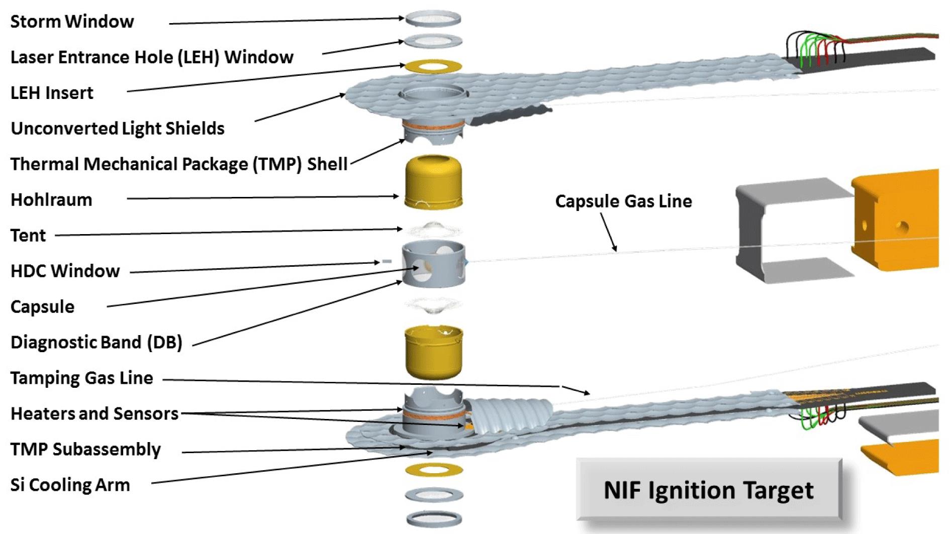
    Fig. 1. A typical NIF target is shown in an exploded view. The work presented here focuses on the assembly of the HR into the TMP subassembly. Each NIF target requires two of these, one upper and one lower assembly.
    The robot cell used for the work presented in this paper is depicted on the left. On the right, in the zoomed-in images, the components to be assembled are shown.
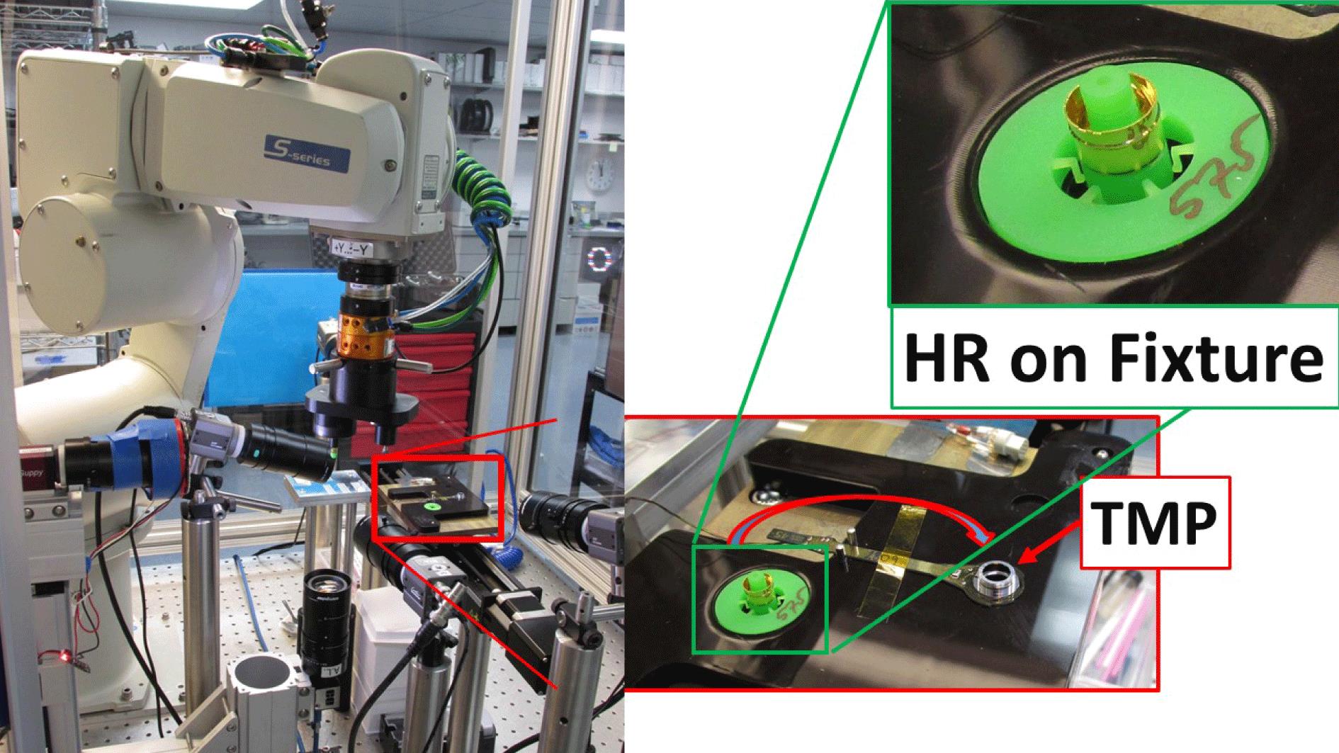
    Fig. 2. The robot cell used for the work presented in this paper is depicted on the left. On the right, in the zoomed-in images, the components to be assembled are shown.
    The fill tube notch on the upper edge of the HR serves as an alignment fiducial to rotate the HR to the correct clocking angle. Two orthogonal cameras are used to correct for fixture tolerances, robot arm position inaccuracies and HR placement errors.
    Fig. 3. The fill tube notch on the upper edge of the HR serves as an alignment fiducial to rotate the HR to the correct clocking angle. Two orthogonal cameras are used to correct for fixture tolerances, robot arm position inaccuracies and HR placement errors.
    The robot arm approaches a surface in small increments (downwards) until contact is detected by the F-T sensor. This sketch shows how the same stamping tool can be used to apply glue on two different component designs without changing the robot program.
    Fig. 4. The robot arm approaches a surface in small increments (downwards) until contact is detected by the F-T sensor. This sketch shows how the same stamping tool can be used to apply glue on two different component designs without changing the robot program.
    Top view of an inserted HR with the 3D printed fixture still in the center of the assembly. The TMP notches serve as an alignment verification fiducial.
    Fig. 5. Top view of an inserted HR with the 3D printed fixture still in the center of the assembly. The TMP notches serve as an alignment verification fiducial.
    A photo of the OCMM microscope is shown. The sample is placed on the microscope slide and measured using pre-programmed recipes.
    Fig. 6. A photo of the OCMM microscope is shown. The sample is placed on the microscope slide and measured using pre-programmed recipes.
    Screen shots from the OCMM metrology routine show measurements of clocking angles on the sample.
    Fig. 7. Screen shots from the OCMM metrology routine show measurements of clocking angles on the sample.
    The HR insertion depth is measured by determining the height of the HR rim over the TMP can datum as shown in this cross-section.
    Fig. 8. The HR insertion depth is measured by determining the height of the HR rim over the TMP can datum as shown in this cross-section.
    The raw data from the HR clocking measurements is presented. Repeated measurements of the clocking angle of the same part gives the expected error of the measurement, while data taken on different assemblies give a measure of repeatability of the robotic insertion process.
    Fig. 9. The raw data from the HR clocking measurements is presented. Repeated measurements of the clocking angle of the same part gives the expected error of the measurement, while data taken on different assemblies give a measure of repeatability of the robotic insertion process.
    Clocking angleInsertion depth
    Standard deviation (degrees) ()
    Metrology (same loc.) 0.01 0.3
    Metrology (diff. loc.) 0.06 0.3
    Robotic insertion$0.43\pm 0.06$$1.5\pm 0.3$
    Table 1. Accuracy for the HR insertion and metrology processes.
    K.-J. Boehm, N. Alexander, J. Anderson, L. Carlson, M. Farrell. Assembly and metrology of NIF target subassemblies using robotic systems[J]. High Power Laser Science and Engineering, 2017, 5(4): 04000e25
    Download Citation