
K.-J. Boehm, N. Alexander, J. Anderson, L. Carlson, M. Farrell. Assembly and metrology of NIF target subassemblies using robotic systems[J]. High Power Laser Science and Engineering, 2017, 5(4): 04000e25
- High Power Laser Science and Engineering
- Vol. 5, Issue 4, 04000e25 (2017)
Abstract
1 Introduction
Shot rates of 0.1–10 Hz on some of the new laser facilities in Europe [e.g., the Extreme Light Infrastructure (ELI) and the Helmholtz International Beamline for Extreme Fields (HIBEF)] will require target production in quantities from dozens to thousands per campaign. These targets need to be precision assembled and subsequently measured. Currently, both operations are done under a microscope by hand. This labor cost is the main contributor to the total cost of a target[
Motivated by the ramp-up of cryogenic fusion experiments on the National Ignition Facility (NIF), General Atomics (GA) started automating the component assembly of targets, see Ref. [
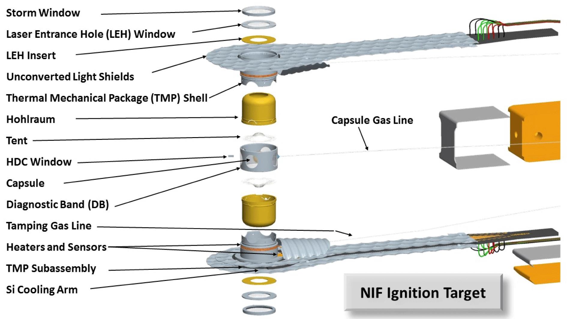
The process of inserting gold hohlraums (HRs) with varying sizes and designs into the TMP is presented in this paper as an example in which a process involving a flexible component design can be automated. Currently, a highly trained technician can insert a gold HR in roughly 2.5 h including measuring and reporting the data. The automated process discussed in this paper does the same in about 30 min.
Sign up for High Power Laser Science and Engineering TOC. Get the latest issue of High Power Laser Science and Engineering delivered right to you!Sign up now
Section
2 Setup and process for automated HR insertion
In general, robotic automation is implemented in processes in which relatively large quantities of the same design are to be produced or assembled justifying the development of tooling and robot programs by significant cost or time savings. Due to the relatively low number of identical targets produced for experiments on the NIF (rarely more than 4 units are of the exact same type), automation of target production processes requires individual customization.
The robot system developed for the HR insertion process described in this work is depicted in Figure
A linear stage with 300 mm of travel is mounted on the optical table to present the specimens to the robot. Multiple HR–TMP pairs can be lined up on that stage and can be driven to the center of the work cell for sequential insertion. Only one pair has been used to date, an example of this is shown on the right in Figure
Also on the optical table is a vision system using two orthogonal cameras used to position the HR to the correct clocking angle as described below and depicted in Figure
The two photos on the right in Figure
In order to benefit from automating this process, the robot system needs to be able to insert a large variety of HR designs without having to change the robot program or the physical setup of the robot work cell. This flexibility is achieved by:generalizing the robot program – all HR designs can be inserted as long as they meet basic NIF cryogenic target design specifications;using 3D printed fixtures to accommodate design changes of target components as these can be produced quickly and inexpensively (the fixtures must interface with the rest of the setup and be easily exchangeable);implementing a feedback loop with an F-T sensor such that surfaces can be approached even if their exact locations are not specified (see Figure
The specifics of the insertion process are described below. After manually loading the HR and the TMP onto a semi-kinematic fixture, it is placed into the working cell of the robot system. Multiple TMPs and HRs could be loaded on a tray side by side as has been done in Ref. [
Using the rubber stamp on the robot end effector a small amount of UV-glue (less than 5 nL) is applied onto the aluminum rim of the TMP that the HR will sit on. Since the exact location of the mating surface varies with the HR’s diameter, the stamp is angled and gets driven down until the F-T sensor is activated as shown in Figure
Next, the HR must be rotated into the proper orientation before insertion into the TMP. A small feature on the HR, the notch which holds the capsule fill tube (see Figure
The tight tolerances on the clocking angle of the finished assembly (
As a next step, the robot moves the HR just above the TMP. After small adjustments of the alignment of the HR to the TMP in the lateral directions, the HR is slowly lowered into the TMP. The vacuum is released, and the HR tool falls through the TMP into a small void in the fixture underneath the TMP opening.
Using the F-T sensor, the robot arm can gently approach the end effector to the upper edge of the HR and then apply a force of 1–1.5 N to ensure proper seating of the HR into the TMP. During this step, the glue between the two parts is squeezed out leaving the parts bonded with a minimal glue bond thickness, see Figure
The glue is cured using a hand-held UV pen while the robot arm is applying force holding the two parts together.
3 Metrology and results
The two most important metrics for a successful insertion are the insertion depth and the clocking of the HR with respect to the TMP. While the former is important to ensure that the two HR halves do not interfere with one another during closing of the target (see Figure
Both the alignment and the insertion depth can be measured using a NEXIV optical coordinate measurement microscope (OCMM) like the one shown in Figure
Using such an automated routine on a NEXIV VMZ machine, both the clocking of the HR inside the TMP (see Figure
Two locations on the silicone arm are used to define the coordinate system of the metrology routine (see Figure
The height is determined by measuring the height along the top surface of the HR and measuring the distance to the datum plane.
The clocking angles between the three components (silicone arm, can and HR) are measured by fitting straight lines along features on the parts that provide a strong black/white contrast on the microscope image as illustrated in Figure
The repeatability of both the robotic insertion as well as the measurement system needed to be determined. Since both the HR and the TMP both have highly reflective surface finishes, even minute changes in light condition between measurements are expected to change the measurement result. Rather than relying on the manufacturer’s specifications, the repeatability of the measurement microscope was determined first. It is important to notice that the results quoted in this work are measured for the specific target design used for these tests. Especially when it comes to clocking accuracy, different HR sizes might yield different repeatability results, both for robotic insertion and subsequent measurements.
A total number of ten measurements were taken using the same HR–TMP assembly. Five of these measurement were taken without moving the sample and five were taken at different locations on the OCMM slide. Based on these results, it was determined that the repeatability of the microscope measuring the insertion depth of this sample was below the
Next, the repeatability of the robot insertion was measured. For this test, the HR was released from the TMP and re-inserted using the procedure outlined in Section
The insertion depth measured for these assemblies is less a measure of the robot’s placement accuracy as it is a measure of the glue bond thickness. The HR’s are driven by the robot arm against a hard stop made up by a step designed into the two parts to be mated. The F-T sensor ensures that the components are held together while the glue is being cured using a UV light source. Similarly, a torus machined into the outside wall of the HR is designed to guide the HR into position to a very tight fit (
| Clocking angle | Insertion depth | |
|---|---|---|
| Standard deviation | (degrees) | ( |
| Metrology (same loc.) | 0.01 | 0.3 |
| Metrology (diff. loc.) | 0.06 | 0.3 |
| Robotic insertion |
Table 1. Accuracy for the HR insertion and metrology processes.
4 Outlook and perspective
The introduction of automation or motorized assistance of target fabrication tasks into high energy density (HED) target fabrication tasks is by far not novel, see Ref. [
The robotic HR assembly process reduces the overall cost of NIF target production and provides an example of the target complexity that can be accommodated while still employing automation.
In contrast to the expected demand for targets for the European HED facilities, current demand of NIF targets is approximately one target per day. However, it is advantageous to put processes in place that are easy to scale up as the shot rate is expected to increase over the next couple of years. Furthermore, GA is motivated to better use skilled technicians and relieve them from mundane tasks.
Development of this process took about 6 months, which falls well within the time frame of preparation for an HED experiment. Especially if the production team is involved early in the design process, vision recognizable features as well as robot tooling interfacing with the components can be developed and tested in parallel.
5 Conclusion
The presentation of the HR insertion process and subsequent metrology demonstrates the feasibility of robotic assembly and qualification measurements of HED Physics target subassemblies.
The ability to use automation to precision assemble targets as presented in this work could have a deep impact on the design of HED targets for high-repetition rated facilities.
Using a robot system equipped with the senses of touch and vision through F-T and camera sensors along with image recognition software, allows for fairly complex planar as well as 3D target designs while alleviating the need for labor intensive assembly processes. The automation of target production processes such as the one demonstrated in this paper could have a major impact on the physical complexity of targets to be shot at high-rep rated facilities.
Target engineers, physicists and users of HED Physics facilities can consider these technologies when balancing the complexity of their experiments with the anticipated cost of target production.
References
[3] G. E. Lee, N. B. Alexander, E. Diaz, J. D. Sheliak. Fusion Sci. Technol., 59, 227(2011).
[4] R. C. Montesani, R. M. Seugling, J. L. Klingmann, E. G. Dzenitis, E. T. Alger, G. L. Miller, R. A. Kent, C. Castro, J. L. Reynolds, M. A. Carrillo. Proceedings of the American Society of Precision Engineering 2008 Annual Meeting(2008).

Set citation alerts for the article
Please enter your email address
© Copyright 2018-2021 | Chinese Laser Press. All Rights Reserved 沪ICP备15018463号-20